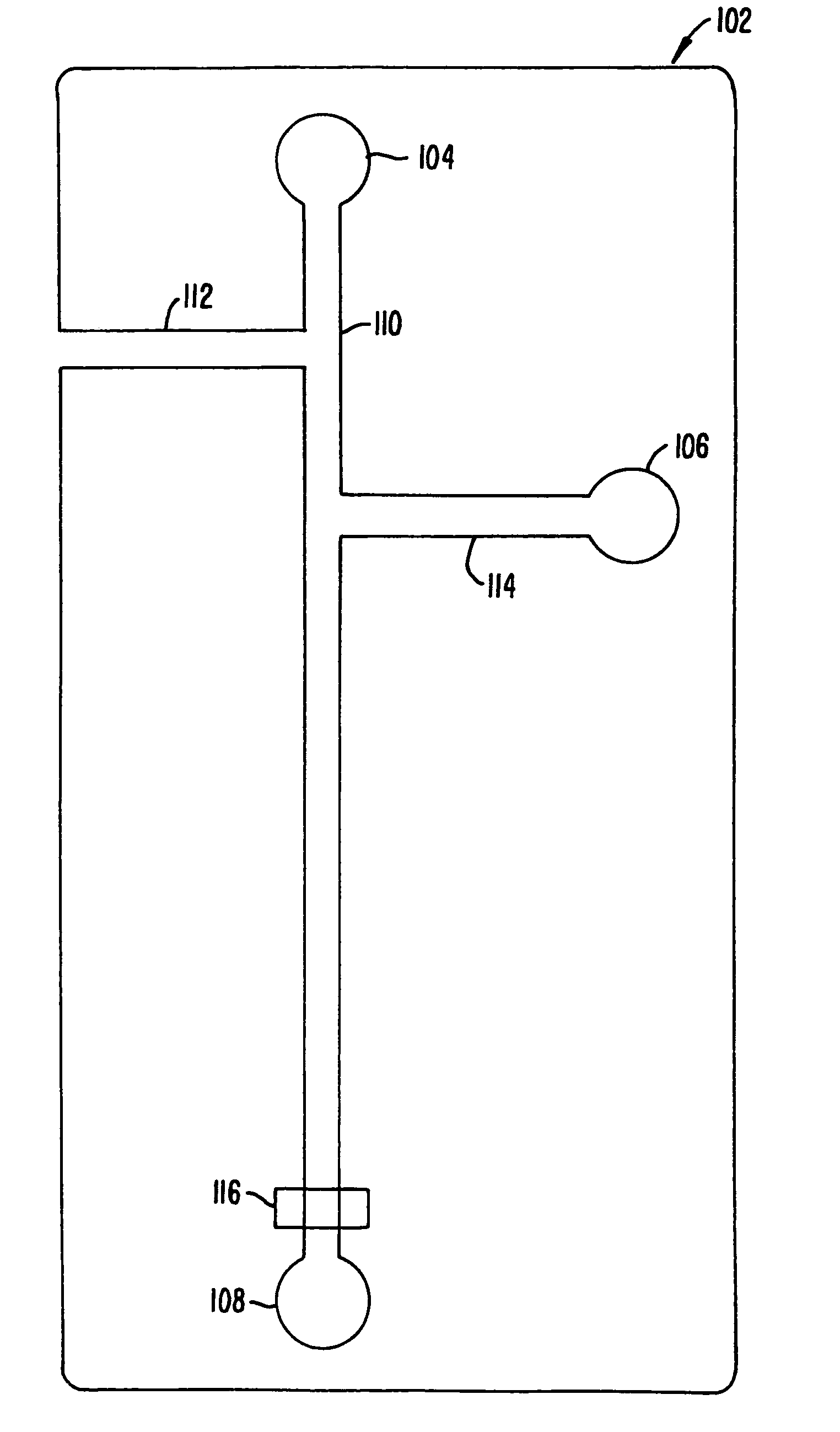
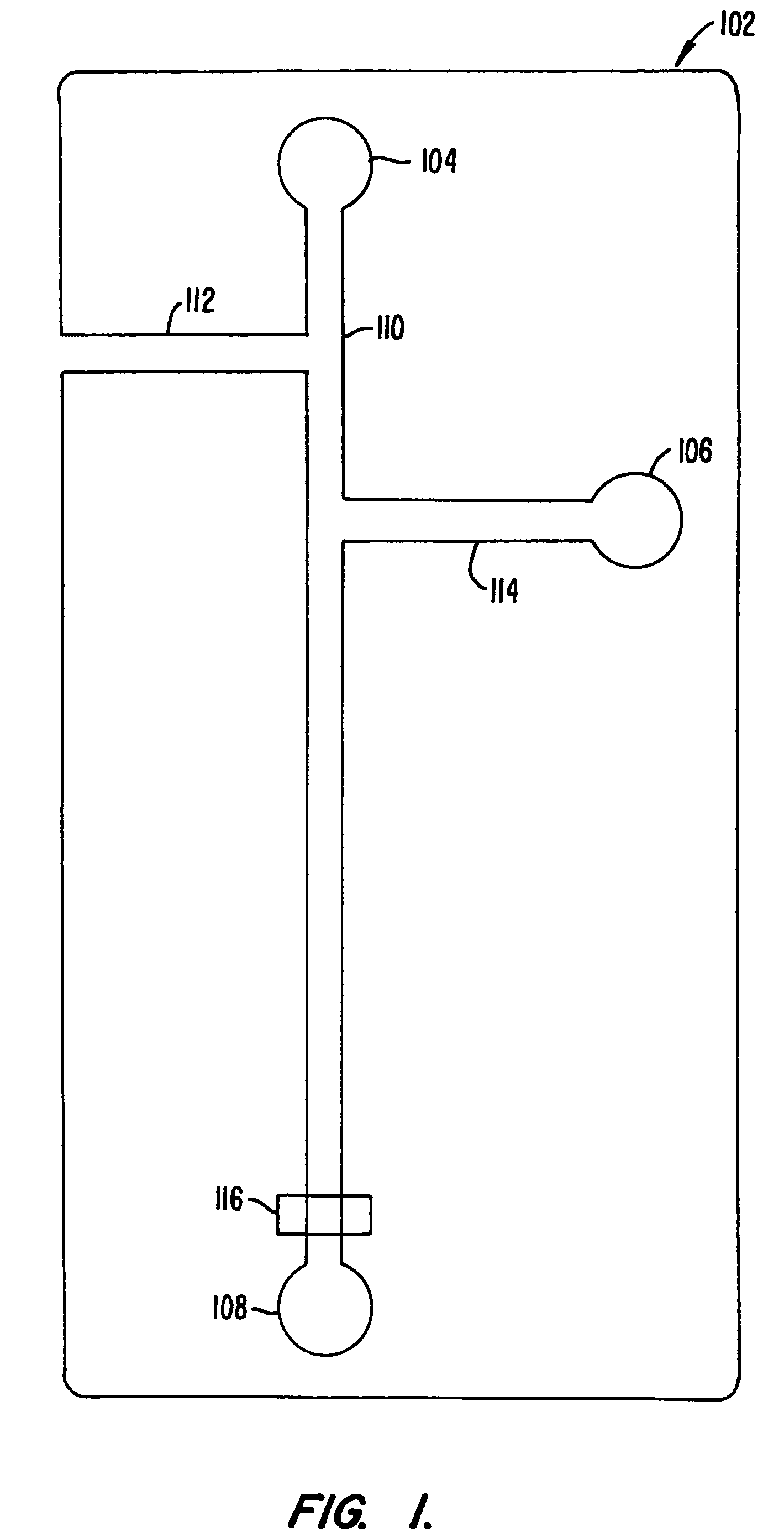
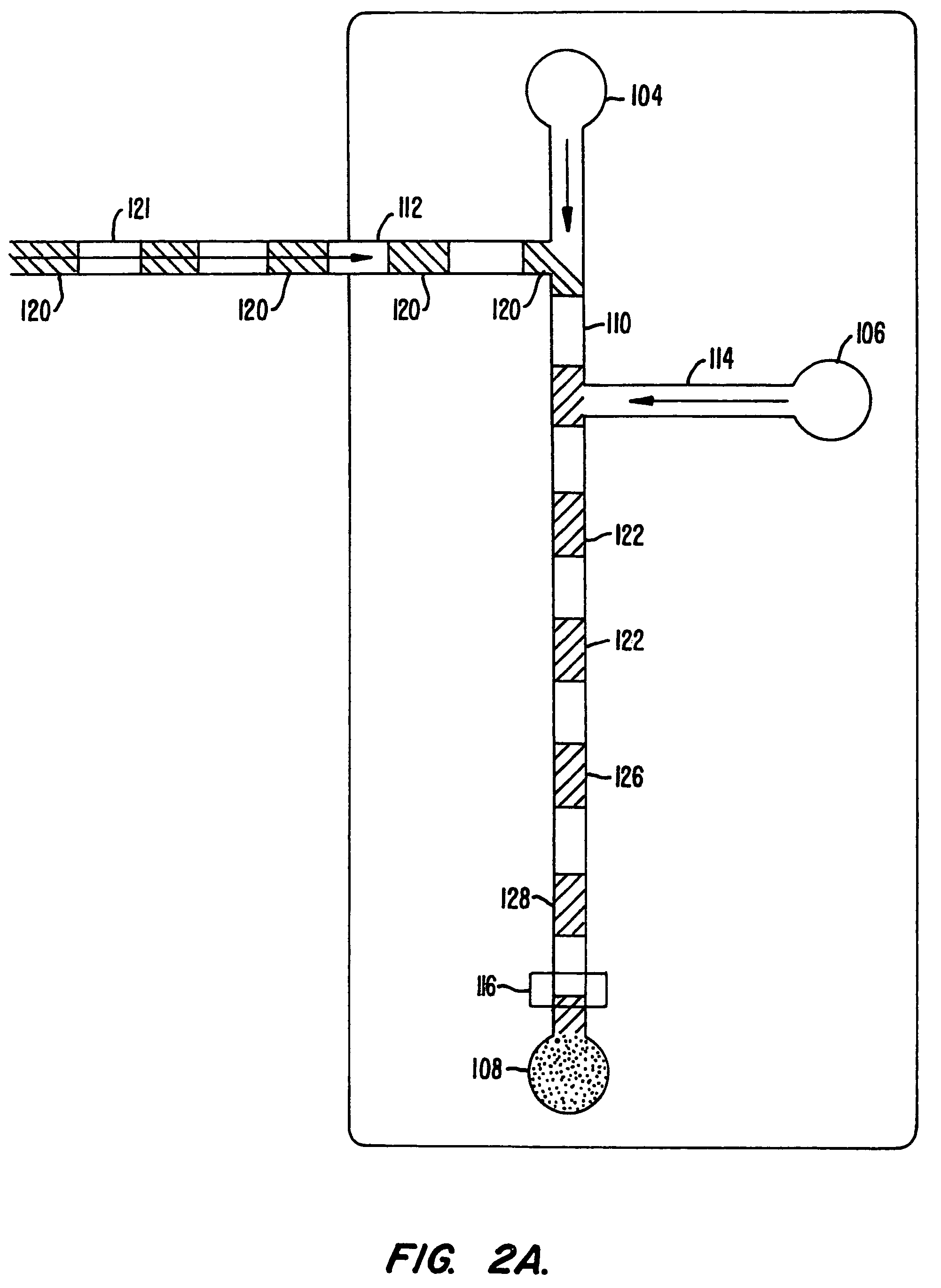
High throughput screening assay systems in microscale fluidic devices

a fluidic device and screening assay technology, applied in the field of apparatus and assay systems for detecting molecular interactions, can solve the problems of poor oral bioavailability, limited drug discovery, and limited assay throughput of modern drugs

Inactive Publication Date: 2006-06-27
CAPLIPER LIFE SCI INC
View PDF2 Cites 101 Cited by
  • Summary
  • Abstract
  • Description
  • Claims
  • Application Information

AI Technical Summary

Problems solved by technology

Specifically, in biological systems the interaction between a receptor and its ligand often may result, either directly or through some downstream event, in either a deleterious or beneficial effect on that system, and consequently, on a patient for whom treatment is sought.
Modern drug discovery is limited by the throughput of the assays that are used to screen compounds that possess these described effects.
Unfavorable pharmacodynamic properties such as poor oral bioavailability and rapid clearance in vivo have limited the more widespread development of peptidic compounds as drugs, however.
Despite the improvements achieved using parallel screening methods and other technological advances, such as robotics and high throughput detection systems, current screening methods still have a number of associated problems.
For example, screening large numbers of samples using existing parallel screening methods have high space requirements to accommodate the samples and equipment, e.g., robotics, etc., high costs associated with that equipment, and high reagent requirements necessary for performing the assays.
Additionally, in many cases, reaction volumes must be very small to account for the small amounts of the test compounds that are available.
Such small volumes compound errors associated with fluid handling and measurement, e.g., due to evaporation, small dispensing errors, or the like.
Additionally, fluid handling equipment and methods have typically been unable to handle these volume ranges with any acceptable level of accuracy due in part to surface tension effects in such small volumes.

Method used


Image

  • High throughput screening assay systems in microscale fluidic devices
  • High throughput screening assay systems in microscale fluidic devices
  • High throughput screening assay systems in microscale fluidic devices

Examples


example 1

Enzyme Inhibitor Screen

[0148]The efficacy of performing an enzyme inhibition assay screen was demonstrated in a planar chip format. A 6-port planar chip was employed having the layout shown in FIG. 8. The numbers adjacent the channels represent the lengths of each channel in millimeters. Two voltage states were applied to the ports of the chip. The first state (State 1) resulted in flowing of enzyme with buffer from the top buffer well into the main channel. The second voltage state (State 2) resulted in the interruption of the flow of buffer from the top well, and the introduction of inhibitor from the inhibitor well, into the main channel along with the enzyme. A control experiment was also run in which buffer was placed into the inhibitor well.

[0149]Applied voltages at each port for each of the two applied voltage states were as follows:

[0150]

State 1State 2Top Buffer Well (I)18311498Inhibitor Well (II)14981900Enzyme Well (III)18911891Substrate Well (IV)14421442Bottom Buffer Well ...

example 2

Screening of Multiple Test Compounds

[0153]An assay screen is performed to identify inhibitors of an enzymatic reaction. A schematic of the chip to be used is shown in FIG. 10. The chip has a reaction channel 5 cm in length which includes a 1 cm incubation zone and a 4 cm reaction zone. The reservoir at the beginning of the sample channel is filled with enzyme solution and the side reservoir is filled with the fluorogenic substrate. Each of the enzyme and substrate are diluted to provide for a steady state signal in the linear signal range for the assay system, at the detector. Potentials are applied at each of the reservoirs (sample source, enzyme, substrate and waste) to achieve an applied field of 200 V / cm. This applied field produces a flow rate of 2 mm / second. During passage of a given sample through the chip, there will generally be a diffusive broadening of the sample. For example, in the case of a small molecule sample, e.g., 1 mM benzoic acid diffusive broadening of approxim...


PUM

PropertyMeasurementUnit
wavelengthsaaaaaaaaaa

Abstract

The present invention provides novel microfluidic devices and methods that are useful for performing high-throughput screening assays. In particular, the devices and methods of the invention are useful in screening large numbers of different compounds for their effects on a variety of chemical, and preferably, biochemical systems.

Description

CROSS-REFERENCE TO RELATED APPLICATIONS[0001]This is a continuation of U.S. patent application Ser. No. 10 / 279,496 filed Oct. 24, 2002, which is a continuation of U.S. patent application Ser. No. 09 / 132,963 filed Aug. 12, 1998, now U.S. Pat. No. 6,479,299, which is a continuation of U.S. patent application Ser. No. 08 / 881,696 filed Jun. 24, 1997, now U.S. Pat. No. 6,267,858, which is a continuation-in-part of U.S. patent application Ser. No. 08 / 671,987 filed Jun. 28, 1996, now U.S. Pat. No. 5,942,443, and U.S. patent application Ser. No. 08 / 761,575 filed Dec. 6, 1996, now U.S. Pat. No. 6,046,056 each of which is hereby incorporated herein by reference in its entirety for all purposes. A PCT Application designating the United States of America, WO 98 / 00231, International Application No. PCT / US97 / 10894 substantially identical to the present application was co-filed in the United States Receiving Office on Jun. 24, 1997. This application is also incorporated herein by reference.FIELD O...

Claims


Application Information

Patent Timeline
Patent Type & Authority Patents(United States)
IPC IPC(8): G01N33/53B01J19/00G01N31/20B01L3/00C12Q1/04C12Q1/25G01N27/26G01N27/27G01N33/50G01N33/566G01N33/574G01N35/08G01N37/00
CPCB01J19/0093B01L3/50273B01L3/502753B01L3/502761B01L3/502784G01N33/5008G01N33/5011G01N33/502G01N33/5064G01N33/5091G01N33/5097G01N33/5304G01N33/57415G01N27/44791Y10T436/25B01J2219/00831B01J2219/00833B01J2219/00853B01J2219/00952B01J2219/00961B01J2219/0097B01L3/5025B01L3/502715B01L2200/027B01L2200/0605B01L2200/0647B01L2200/0668B01L2200/0673B01L2300/0816B01L2300/0861B01L2300/0864B01L2300/0867B01L2300/0877B01L2300/0887B01L2400/0415B01L2400/0418B01L2400/0487G01N35/08Y10S366/02Y10S435/81Y10S436/804Y10S435/817Y10S436/805Y10S436/806Y10T436/11Y10T436/113332Y10T436/110833Y10T436/117497B01J2219/00828
Inventor PARCE, J. WALLACEKOPF-SILL, ANNE R.BOUSSE, LUC J.
Owner CAPLIPER LIFE SCI INC
Why Eureka
Try Eureka