Facial aesthetic treatment apparatus

a facial and treatment device technology, applied in the field of facial aesthetic treatment devices, can solve the problems of bringing about undesired pain or even bruises, and difficulty in removing the attachment from the skin,

Inactive Publication Date: 2001-11-20
MATSUSHITA ELECTRIC WORKS LTD
View PDF11 Cites 80 Cited by
  • Summary
  • Abstract
  • Description
  • Claims
  • Application Information

AI Technical Summary

Benefits of technology

In one preferred embodiment, the regulator comprises a bypass suction path extending from the suction pump to an open-air end which is accessible by a finger of a user's hand grasping the housing so as to selectively close and open said open-air end. Thus, the bypass suction path can be immediately opened simply by releasing a finger, i.e., a thumb of the user's hand gripping the housing from the open-air end. Therefore, the user can be easy to minimize the suction force, thereby facilitating to stop applying the suction force in a prompt response to the user's intention. Further, since the open-air end can be closed as well simply by placing the thumb closely on the open-air end, it is easy and convenient to apply the suction force intermittently while moving the attachment across a wide area of the facial skin, giving rise to an improved handling of the apparatus.
A flexible cover may be provided on the exterior of the housing to be accessible by the finger of the user for closing the opening the open-air end. With the use of the cover, the open-air end can be free from foreign matter which might otherwise clog the open-air end.
Further, the regulator may comprise a contractible bypass suction path extending from the suction pump to an open end, and a mechanism of floatingly supporting the nozzle to the housing for allowing the nozzle to move between an extended position of causing the attachment to be disengaged from the facial skin and a retracted position of causing the attachment to be held in pressed contact with the facial skin. The nozzle is forced into the retracted position as a consequence of pressing the attachment against the skin, thereby closing the bypass suction path for applying the suction force to the skin. When the user moves the housing away from the skin, the nozzle is forced into the extended position as the attachment still stick to the skin due to the sucking force. Immediately upon the nozzle moving into the extended position, the bypass suction path is opened to release the suction force, thereby allowing the attachment to be readily disengaged from the skin for safe and rapid removal of the attachment from the skin.
In another embodiment, the regulator comprises a resilient tube extending from the nozzle to an open-air end to define the bypass suction path, and an actuator held in contactable relation with a portion of the resilient tube for pressing it to close the bypass suction path to a varying extent. Thus, the suction force being applied to the skin can be adjusted from maximum to minimum for an optimum facial treatment as well as for safe removal of the attachment from the skin.
In this connection, the actuator is mounted to the housing which is of an elongated configuration having a longitudinal axis. The actuator includes a pair of button sections exposed on an exterior of the housing to be accessibly by a finger of the user's hand gripping the housing. The pair of the button sections are arranged on opposite sides of the housing about the longitudinal axis such that both of a left-handed and right-handed user can be easy to manipulate the actuator in an convenient manner for adjusting the suction force.

Problems solved by technology

When applying the suction force over a prolonged time to a delicate portion of the skin, there remains a possibility of bringing about undesired pain or even bruise, i.e., purpuric mark in the skin portion as a result of that the sucked portion of the skin is forced to bulge to such an extent of breaking capillary vessels in that portion.
Otherwise the suction force would continue being applied to the skin even after turning off the switch handle, thereby making it difficult to remove the attachment from the skin.

Method used


Image

  • Facial aesthetic treatment apparatus
  • Facial aesthetic treatment apparatus
  • Facial aesthetic treatment apparatus

Examples


first embodiment

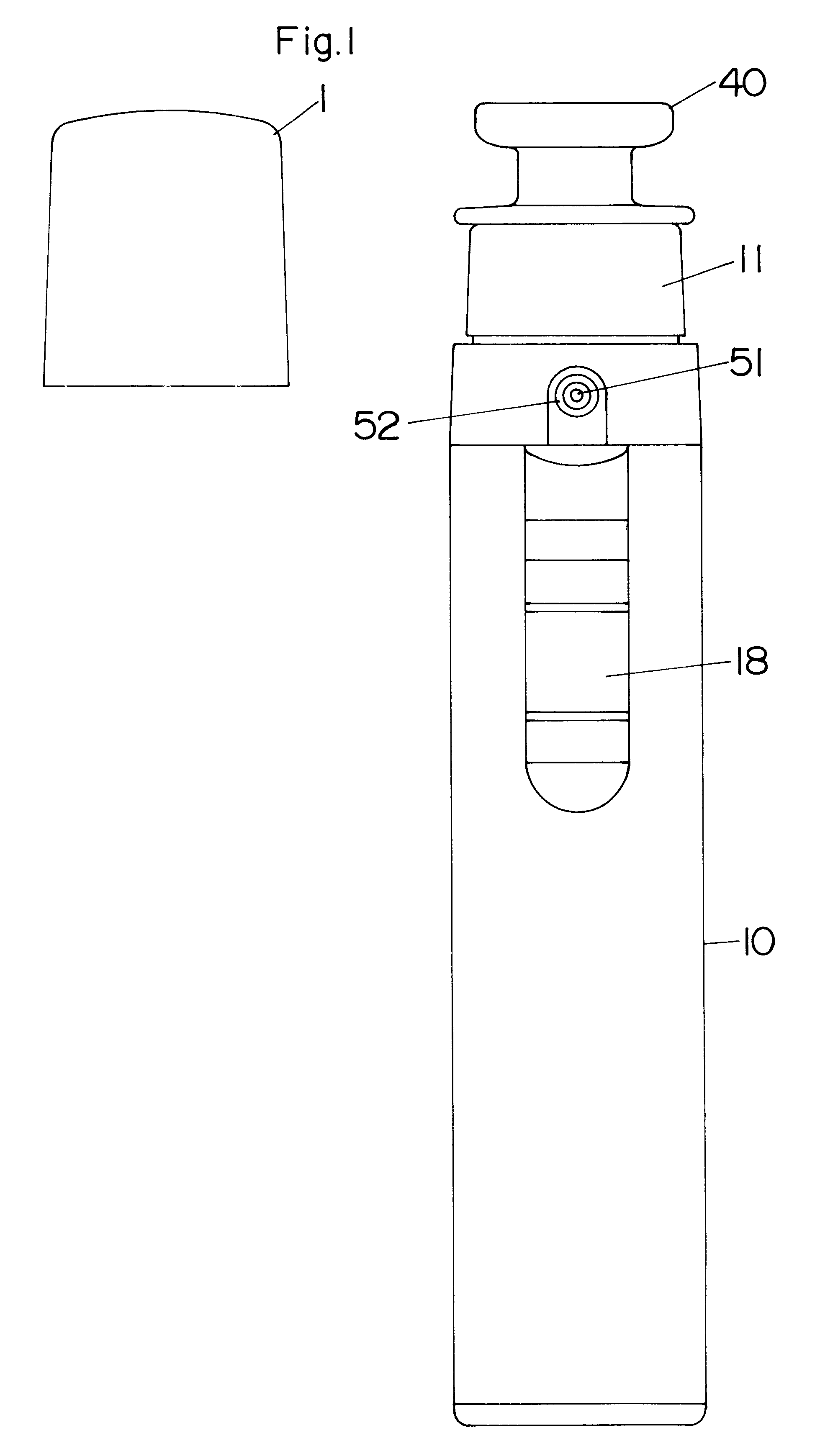
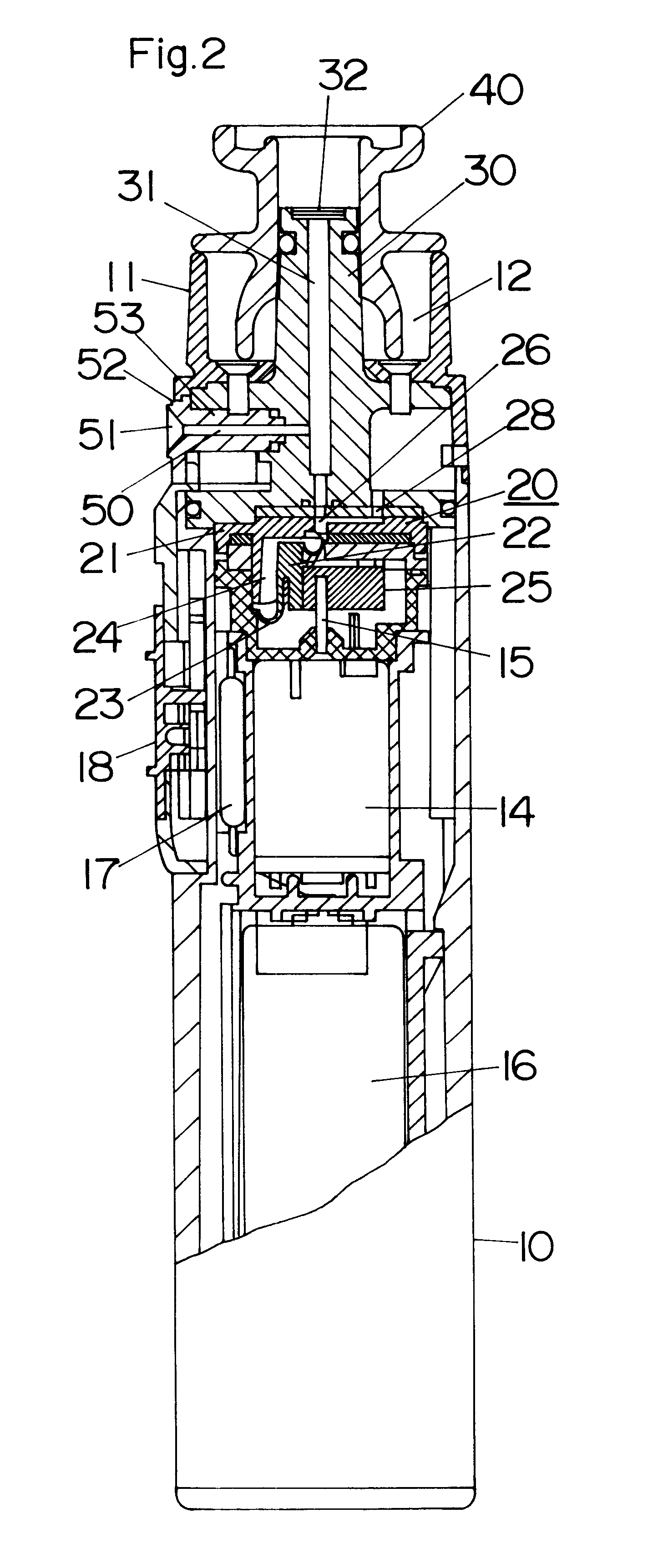
Referring now to FIG. 1, there is shown a facial aesthetic treatment apparatus in accordance with a first embodiment of the present invention. The apparatus is composed of a elongated housing 10 shaped to be gripped by a hand of a user, and an attachment 40 adapted in use to apply a vacuum to a facial skin for removing a dirt, sebum or the like debris from the skin. The housing 10 is of an elongated configuration having a longitudinal axis and incorporates therein a diaphragm pump 20, a motor 14 driving the pump, and a battery 16 energizing the motor which are aligned along the longitudinal axis of the housing. Formed at the upper end of the housing 10 is a head 11 with a recess 12 through which a nozzle 30 extends for detachably carrying the attachment 40 at its upper end. The nozzle 30 is secured at its lower base to the housing 10 and has a through-hole 31 extending along the longitudinal axis of the housing. A cap 1 is provided on the top end of the housing to cover the attachme...

second embodiment

FIGS. 5A and 5B show a facial aesthetic treatment apparatus in accordance with a second embodiment of the present invention which is identical to the first embodiment except that a switch handle 18A is configured to have a shutter section 19 at its upper end for selectively opening and closing an open-air end 51A of a like bypass suction path 50A. Like parts are designated by like numerals with a suffix letter of "A". The switch handle 18A is slidable between an OFF-position (FIG. 5A) of deenerging the motor 14A to stop the pump 20A and an ON-position (FIG. 5B) of energizing the motor 14A to operate the pump 20A. The shutter section 19 formed as an integral part of the switch handle 18A closes the open-air end 51A as the switch handle 18A comes into the ON-position, and opens the open-air end 51A as the switch handle 18A comes into the OFF-position. Thus, the negative pressure being applied to the skin portion through the attachment can be released as soon as the switch handle 18A i...

third embodiment

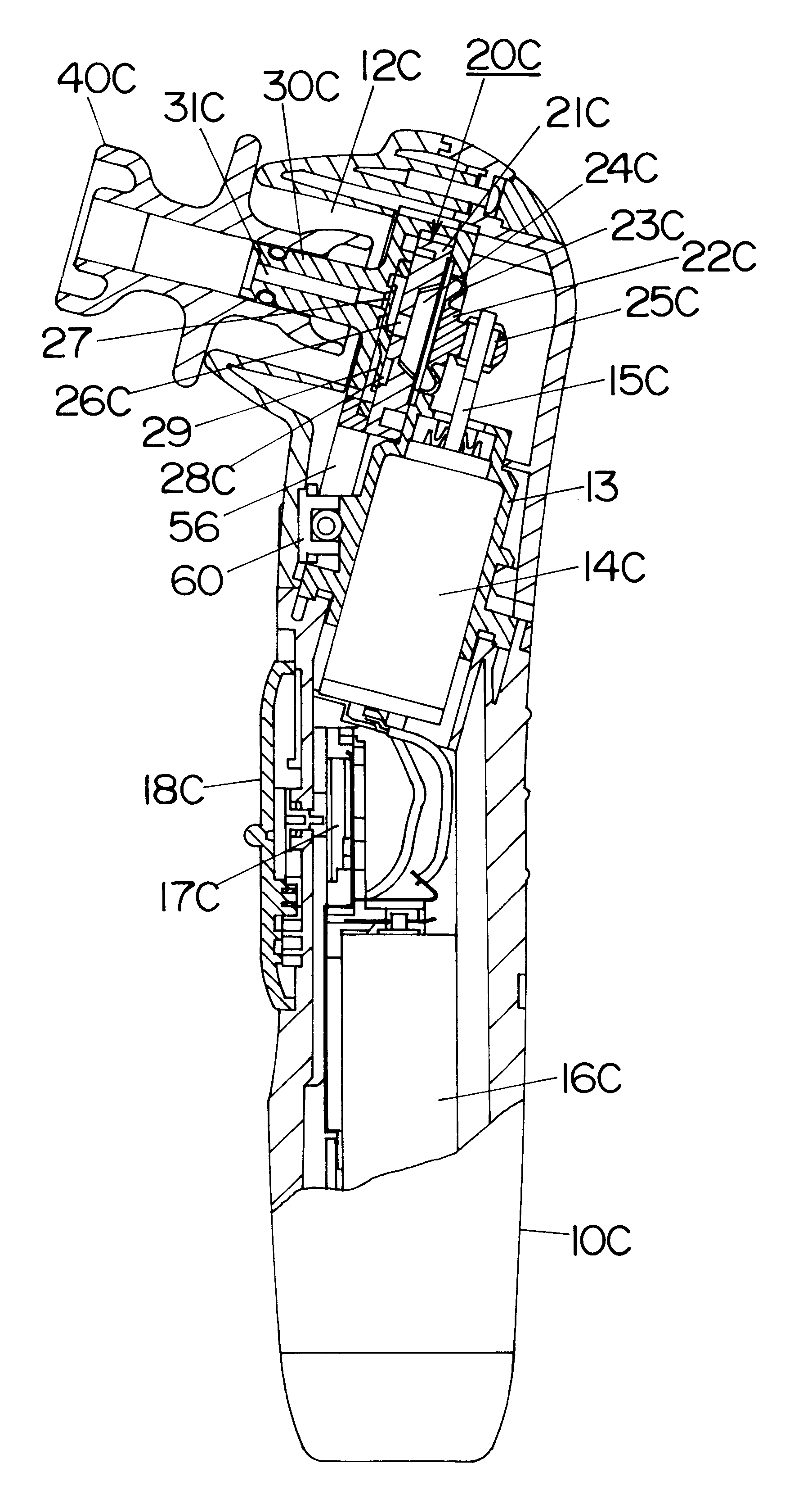
FIGS. 6A and 6B show a facial aesthetic treatment apparatus in accordance with a third embodiment of the present invention which is identical to the first embodiment except that a nozzle 30B is floatingly supported to the housing 10B to define a contractible bypass suction path 50B between the nozzle and a base 34 supporting the nozzle. Like parts are designated by like numerals with a suffix letter of "B". The base 34 is secured to the housing 10B to extend over the pump 20B and is coupled to the nozzle 30B by means of a resilient bellows 35 such that the nozzle 30B is axially movable between a retracted position of FIG. 6B and an extended position of FIG. 6A. In the absence of an external force, the nozzle 30 is retained at the extended position by resiliency given to the bellows 35 where the lower end of the nozzle 30A is spaced from the base 34 to define therebetween the contractible bypass suction path 50B communicating the through-hole 31A of the nozzle 30A with an outside air...


PUM


Abstract

A facial aesthetic treatment apparatus includes a housing provided with a nozzle and a suction pump for developing a suction force. An attachment is mounted to the nozzle for applying the suction force to a facial skin for removal of sebum, dirt or the like debris from the facial skin. The apparatus is capable of regulating the suction force being applied to the skin, and particularly minimizing the suction force immediately in response to the user's action of ceasing the treatment, thereby making it easy to remove the attachment from the facial skin and therefore reducing a risk of causing a pain and leaving the purpuric mark as well. A regulator is incorporated to regulate the suction force being applied to the facial skin for easy and safe removal of the suction force.

Description

BACKGROUND OF THE INVENTION 1. FIELD OF THE INVENTIONThe present invention is directed to a facial aesthetic treatment apparatus for removing sebum, dirt or the like debris from a facial skin by application of air suction to the skin, and more particularly to such apparatus with a capability of adjusting the suction force. 2. Description of the Prior ArtAs disclosed in Japanese Utility Model Publication No. 5-37234, a prior facial aesthetic treatment apparatus is known to include a housing incorporating a suction pump for developing a suction force and an attachment adapted in use to be placed in contact with a facial skin for applying the suction force in order to remove the sebum or the like debris. When applying the suction force over a prolonged time to a delicate portion of the skin, there remains a possibility of bringing about undesired pain or even bruise, i.e., purpuric mark in the skin portion as a result of that the sucked portion of the skin is forced to bulge to such an...

Claims


Application Information

Patent Timeline
Patent Type & Authority Patents(United States)
IPC IPC(8): A61M1/00A61M1/06A61H7/00
CPCA61M1/0047A61M1/06A61M1/08A61M1/0072A61M2210/0606A61M1/7411A61M1/82A61H7/00
Inventor ITO, KENGOIKADAI, KAZUYASU
Owner MATSUSHITA ELECTRIC WORKS LTD
Why Eureka
Try Eureka