Compact imaging device incorporating rotatably mounted cameras

a compact imaging and camera technology, applied in the direction of instruments, television systems, individual entry/exit registers, etc., can solve the problems of insufficient speed for quick transactional activities, insufficiently clear, properly aligned images, and insufficient optical systems to rapidly acquire clear and accurate images

Inactive Publication Date: 2001-11-20
SENSAR
View PDF17 Cites 173 Cited by
  • Summary
  • Abstract
  • Description
  • Claims
  • Application Information

AI Technical Summary

Problems solved by technology

While this procedure is satisfactory for some applications, it is not satisfactory for quick transactional activities such as using an automated teller machine, automated cash dispensing machine or certain access control applications since it requires cooperation from the user.
However, prior to the present invention or U.S. Pat. No. 5,717,512 to Chmielewski et al, there has not been an optical system which could rapidly acquire a sufficiently clear, properly aligned image of an iris of the person to be identified unless that person positioned his eye in a fixed position relatively close to an imaging camera

Method used


Image

  • Compact imaging device incorporating rotatably mounted cameras
  • Compact imaging device incorporating rotatably mounted cameras
  • Compact imaging device incorporating rotatably mounted cameras

Examples


Embodiment Construction

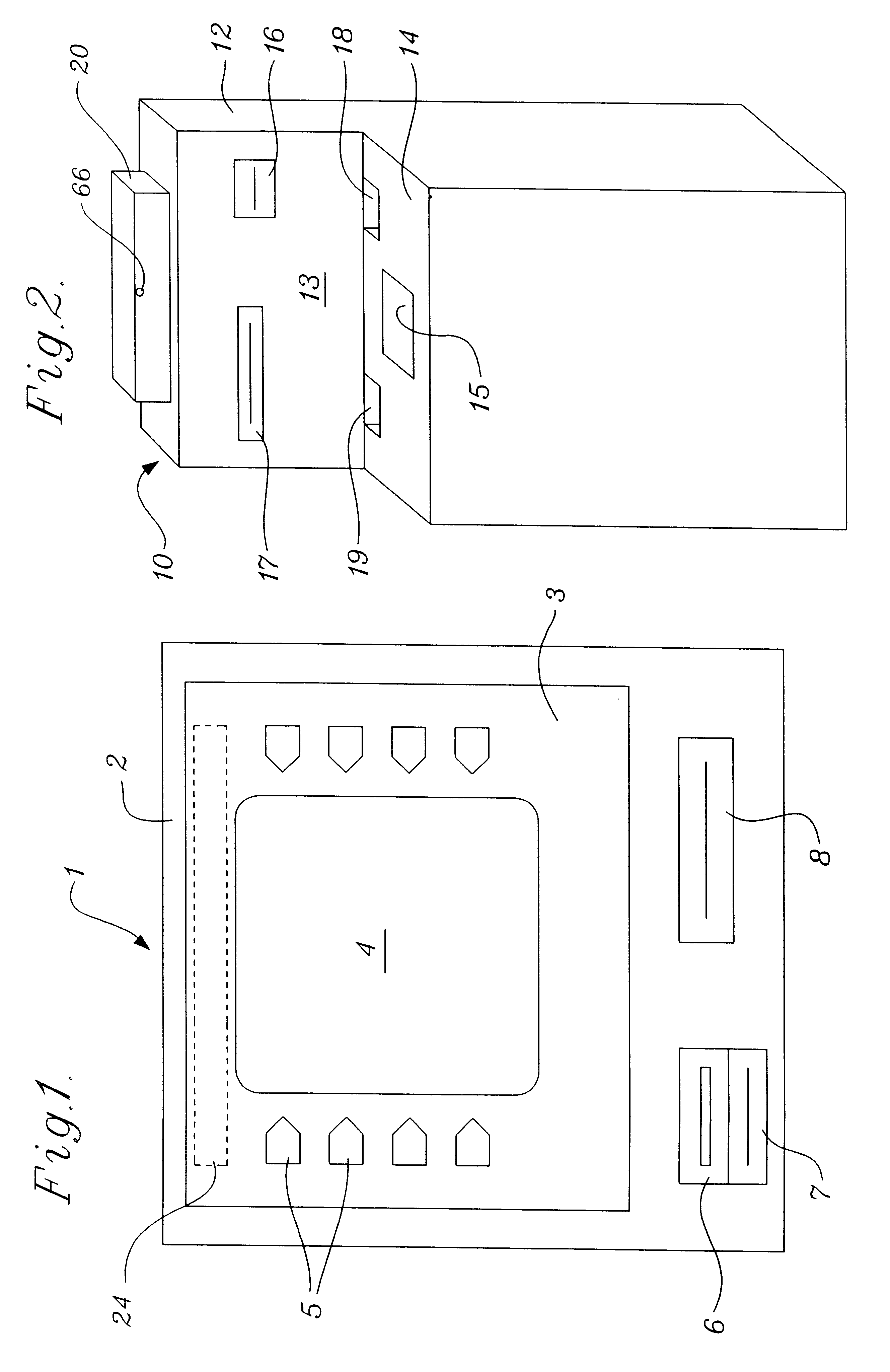
Two basic types of automated teller machines are illustrated in FIGS. 1 and 2. In FIG. 1 there is shown an automated teller machine of the type manufactured by NCR. That machine 1 has a console 2 containing a CRT display 4. Adjacent to the display are transaction selection buttons 5 in a cover plate 3 which surrounds the CRT display 4. A card dip 6 and receipt printer are positioned below the cover plate 3. A currency dispenser 8 is positioned adjacent the card dip. It should be understood that the console could be configured so that the card dip 6, printer 7 and currency dispenser 8 are on the right side or left side of the cover 3. The cabinet for the NCR machine is designed to be positioned in a wall of a building or may be configured as part of a freestanding ATM.

The automated teller machine shown in FIG. 2 is a stand alone device such as is manufactured by OKI Electric. That machine has a cabinet 12 which sits on the floor. The cabinet has a vertical face 13 in which the card d...


PUM


Abstract

A compact image steering and focusing device has a generally rectangular frame containing at least one illuminator and at least one and preferably two cameras and a pan/tilt mirror on a tilting frame. There is a tilt axis through the frame. A tilt motor is attached to the frame to turn the frame about the tilt axis. Another camera is positioned in optical alignment with the pan/tilt mirror. The device can fit behind the cover plate of an automated teller machine. Images from the cameras on the titling frame are used to focus the other camera on one eye of the automated teller machine user to identify the user by iris analysis and comparison to an iris image or iris code on file.

Description

1. Field of the InventionThe invention relates to a device for intelligently directing light to a particular object in a scene and then directing the light reflected from the object into an imaging camera.2. Background of the InventionThere are several methods known as biometrics used for verifying or recognizing the identity an individual. Verification is a one-to-one process in which a computed biometric code from an individual is compared to a single previously stored biometric code to determine if the person is who he or she claims to be. Recognition is a one-to-many process in which a computed biometric code from an individual is compared to a data base of many different individuals' biometric codes with the objective of determining the identity of the individual. Biometric methods include analyzing a signature, obtaining and analyzing an image of a fingerprint and imaging and analyzing the retinal vascular patterns of a human eye. Recently, the art has used the iris of the eye...

Claims


Application Information

Patent Timeline
IPC IPC(8): G02B26/10G07C9/00G06K9/00G07F19/00H04N5/225H04N13/00H04N13/239
CPCG02B26/10G06K9/00604G07C9/00158G07F19/20G07F19/201G07F19/207H04N5/2251H04N5/2256H04N13/0207H04N13/0239H04N13/0253H04N13/0296H04N13/0246H04N2013/0081H04N13/254H04N13/246H04N13/207H04N13/296H04N13/239G07C9/37G06V40/19H04N23/56H04N23/55
Inventor VAN SANT, GLENNEGIN, MICHAELDROZD, JOHNCHMIELEWSKI, JR., THOMAS A.KAIGHN, KEVIN CARL
Owner SENSAR
Why Eureka
Try Eureka