System and method for measuring and controlling rotation of coiled tubing

a technology of coiled tubing and measuring system, which is applied in the direction of drilling pipes, drilling rods, instruments, etc., can solve the problems further bending of coiled tubing, and damage to coiled tubing, etc., to achieve accurate determination of coiled tubing fatigue life and/or deformation

Inactive Publication Date: 2001-11-27
COILED TUBING ENG SERVICES
View PDF41 Cites 91 Cited by
  • Summary
  • Abstract
  • Description
  • Claims
  • Application Information

AI Technical Summary

Benefits of technology

New, useful, unique, efficient, non-obvious systems and methods for accurately determining coiled tubing fatigue life and / or deformation;

Problems solved by technology

The injection operation often results in further bending of the coiled tubing.
Repeated bending cycles can damage the coiled tubing.
The internal pressure and axial loads can exacerbate this damage.
This damage, known as fatigue damage, accumulates until the coiled tubing eventually fails.
Coiled tubing is fatigued and / or deformed when it is run in and out of a hole or bore particularly from bending and straightening at the reel and / or gooseneck.
In some coiled tubing operations the length of the fatigue life strongly affects the economics of the operation.
The coiled tubing is expensive, and must be replaced at the end of its fatigue life or when it has become too deformed to be used.
Fatigue factors for coiled tubing include the radii of bending, diameter, wall thickness and length of the coiled tubing.
Such changes are permanent deformations that can cause problems when using the coiled tubing.
Prior art fatigue tracking systems do not take this rotation into account when calculating fatigue damage and deformation.
Thus, in such tests, the impact of rotation on fatigue life and deformation was not measured.
This testing revealed that in many cases rotation increases the fatigue life.
When the coiled tubing is being used, rotation is random and uncontrolled.
This random rotation may increase the fatigue life.
With the current systems which do not take rotation into account, coiled tubing may be scrapped earlier than necessary, sometimes at a large cost to the industry.

Method used


Image

  • System and method for measuring and controlling rotation of coiled tubing
  • System and method for measuring and controlling rotation of coiled tubing
  • System and method for measuring and controlling rotation of coiled tubing

Examples


Embodiment Construction

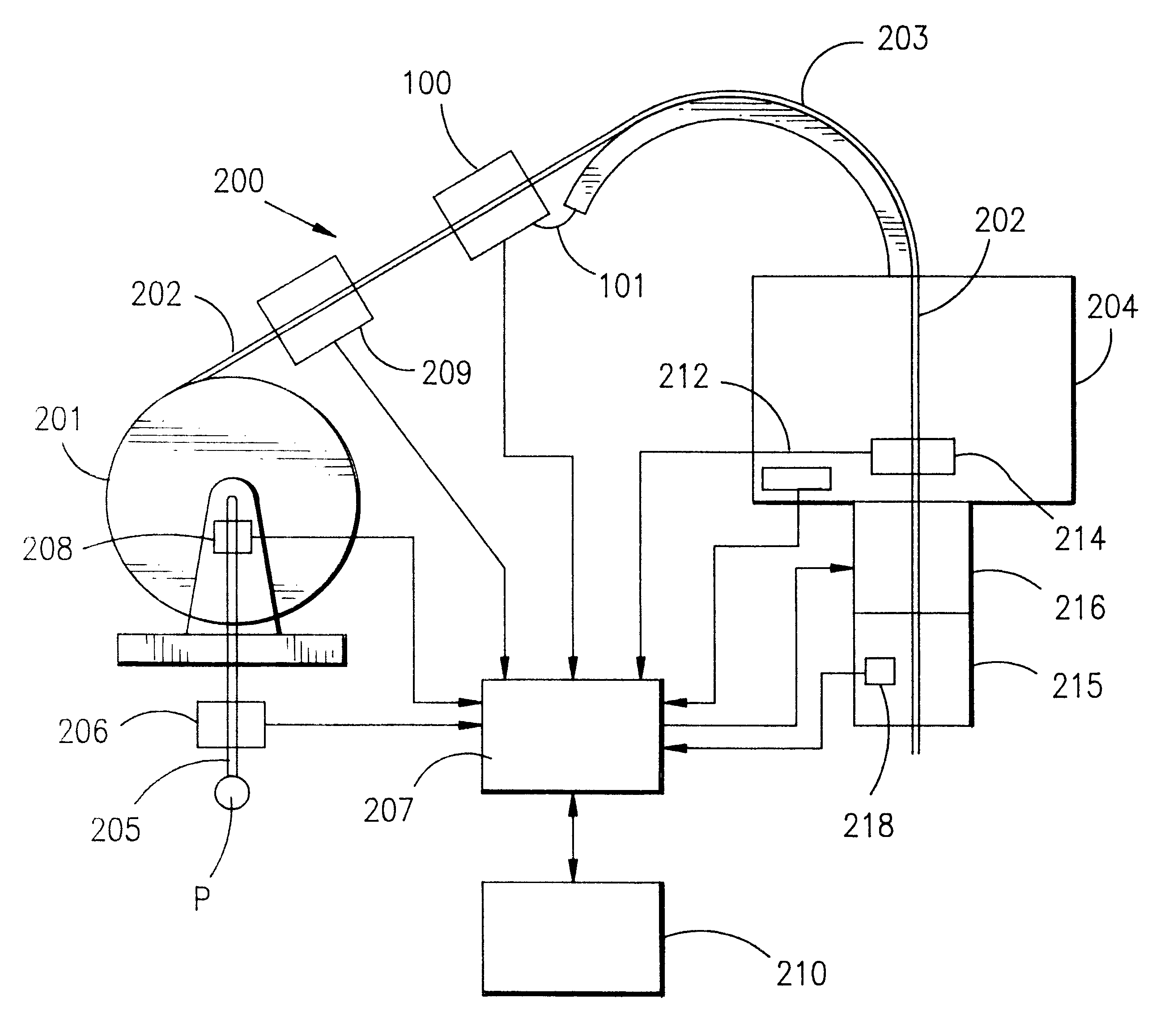
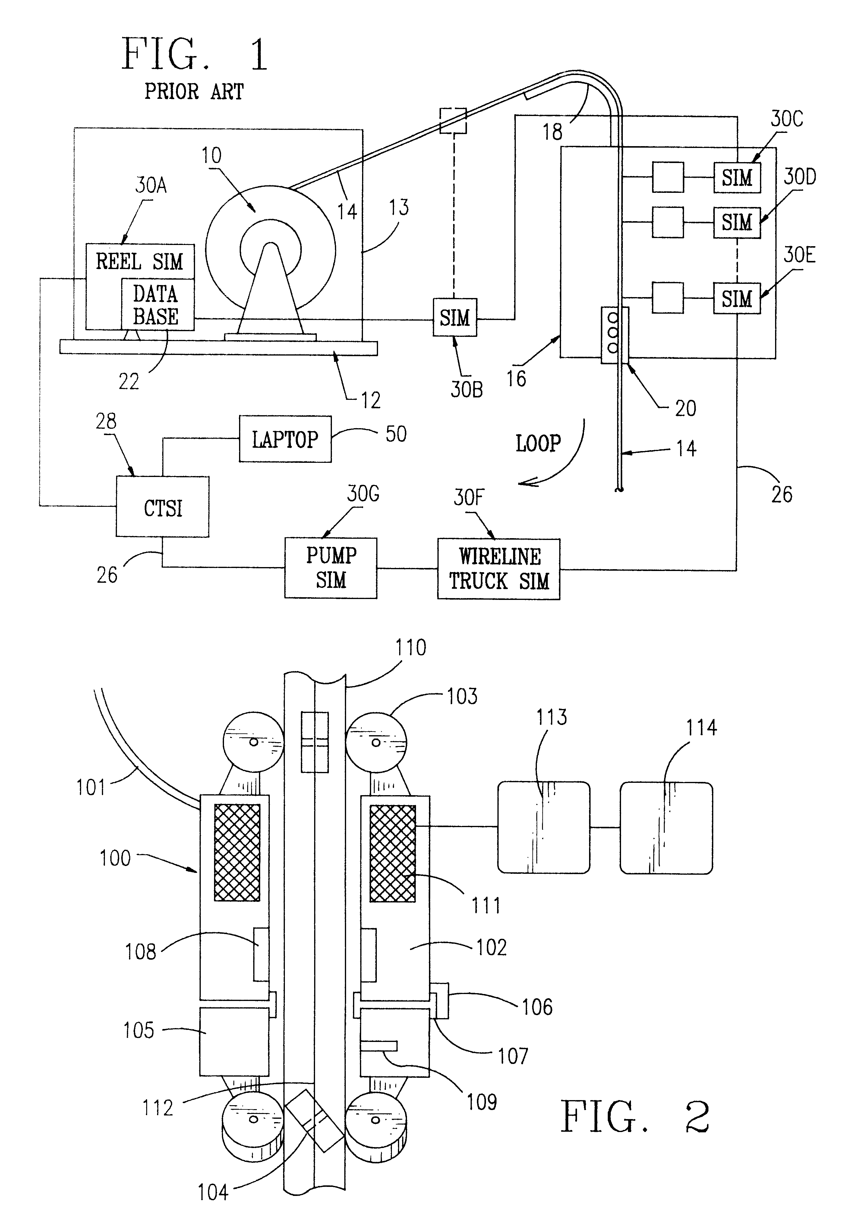
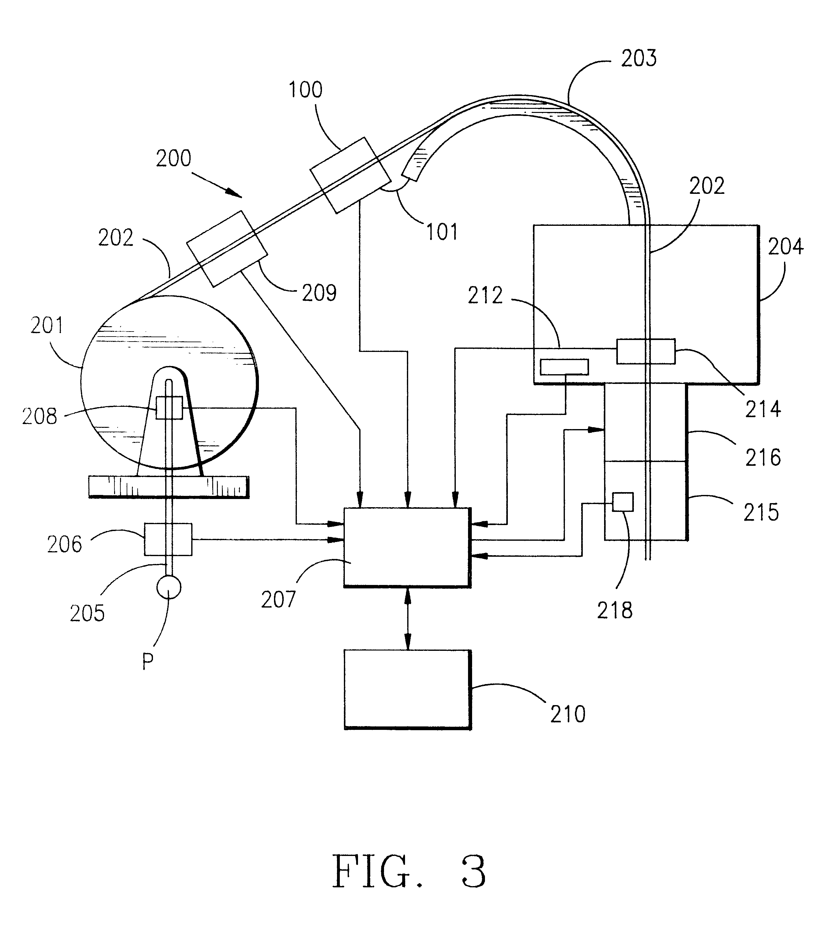
FIG. 2 shows a sensor apparatus 100 for measuring the rotational orientation of coiled tubing using a Hall effect sensor 109 to locate a longitudinal seam weld 112 on coiled tubing 110. Of course, it is within the scope of this invention to employ one or more of any known suitable sensors as discussed above. A support arm 101 attaches the sensor apparatus 100 to a non-moving structure, e.g. but not limited to a guide arch 18 as in FIG. 1. The support arm 101 prevents a non-rotating housing 102 from moving with coiled tubing 110, or rotating about the coiled tubing. A set of wheels 103 attached to the non-rotating housing 102, roll as the coiled tubing 110 moves through the sensor apparatus 100. Another set of wheels 104 are attached to a rotating sensor head 105. These wheels 104 are at an angle to the axis of the coiled tubing 110, causing the rotating sensor head 105 to rotate whenever the coiled tubing 110 moves. A rotational position sensor 106 connected to the non-rotating hous...


PUM

PropertyMeasurementUnit
lengthaaaaaaaaaa
pressureaaaaaaaaaa
thicknessaaaaaaaaaa

Abstract

The present invention, in certain embodiments, discloses an apparatus for determining characteristics of coiled tubing that is run in and out of a bore, e.g. a wellbore, for calculating fatigue life of the coiled tubing, the apparatus having a reel structure for said coiled tubing including a reel on which said coiled tubing is wound and a frame supporting the reel for rotation, an injector structure for running the coiled tubing from the reel structure into said bore and for withdrawing said coiled tubing from the bore, sensor apparatus for continuously monitoring sensing and recording rotation of said coiled tubing and for measuring amount of said rotation, said sensor apparatus including apparatus for receiving and transmitting data relating to said characteristics of the coiled tubing, and a computer apparatus for receiving data from said sensor apparatus and processing said data to determine fatigue life of said coiled tubing.

Description

1. Field Of The Invention2. Description of Related ArtCoiled tubing is pipe which can be run in and out of a bore, pipeline, tubular string, borehole, or wellbore. In certain embodiments, the coiled tubing is made of plastic, composites, titanium or steel. The tubing is stored on a reel and in winding onto the reel it is bent. Typically the coiled tubing is fed from the reel over a gooseneck of an injector for directing the tubing into a bore hole. The injection operation often results in further bending of the coiled tubing. Often there is some internal pressure inside the coiled tubing while it is being bent. Also axial loads are applied to the coiled tubing both while it is being bent and while it is straight. Repeated bending cycles can damage the coiled tubing. The internal pressure and axial loads can exacerbate this damage. This damage, known as fatigue damage, accumulates until the coiled tubing eventually fails. Failure is defined as the point at which the coiled tubing can...

Claims


Application Information

Patent Timeline
Patent Type & Authority Patents(United States)
IPC IPC(8): E21B19/22E21B19/00G01N3/00G01N3/26G01N3/32G01N3/02
CPCE21B19/22G01N3/26G01N3/32G01N2203/0021G01N2203/0218G01N2203/0248
Inventor NEWMAN, KENNETH R.
Owner COILED TUBING ENG SERVICES
Why Eureka
Try Eureka