Machine safety guard

a technology for safety guards and machines, applied in the field of shields, can solve problems such as increased manufacturing costs and operator injuries

Inactive Publication Date: 2001-12-04
RITE HITE HLDG CORP
View PDF48 Cites 103 Cited by
  • Summary
  • Abstract
  • Description
  • Claims
  • Application Information

AI Technical Summary

Problems solved by technology

Industrial machinery can cause injuries to operators thereof if they are caught within the operative parts of the machinery or struck by elements emanating from such machinery.
It is often difficult and time-consuming to remove safety guards to gain access to the machine to change it

Method used


Image

  • Machine safety guard
  • Machine safety guard
  • Machine safety guard

Examples


Embodiment Construction

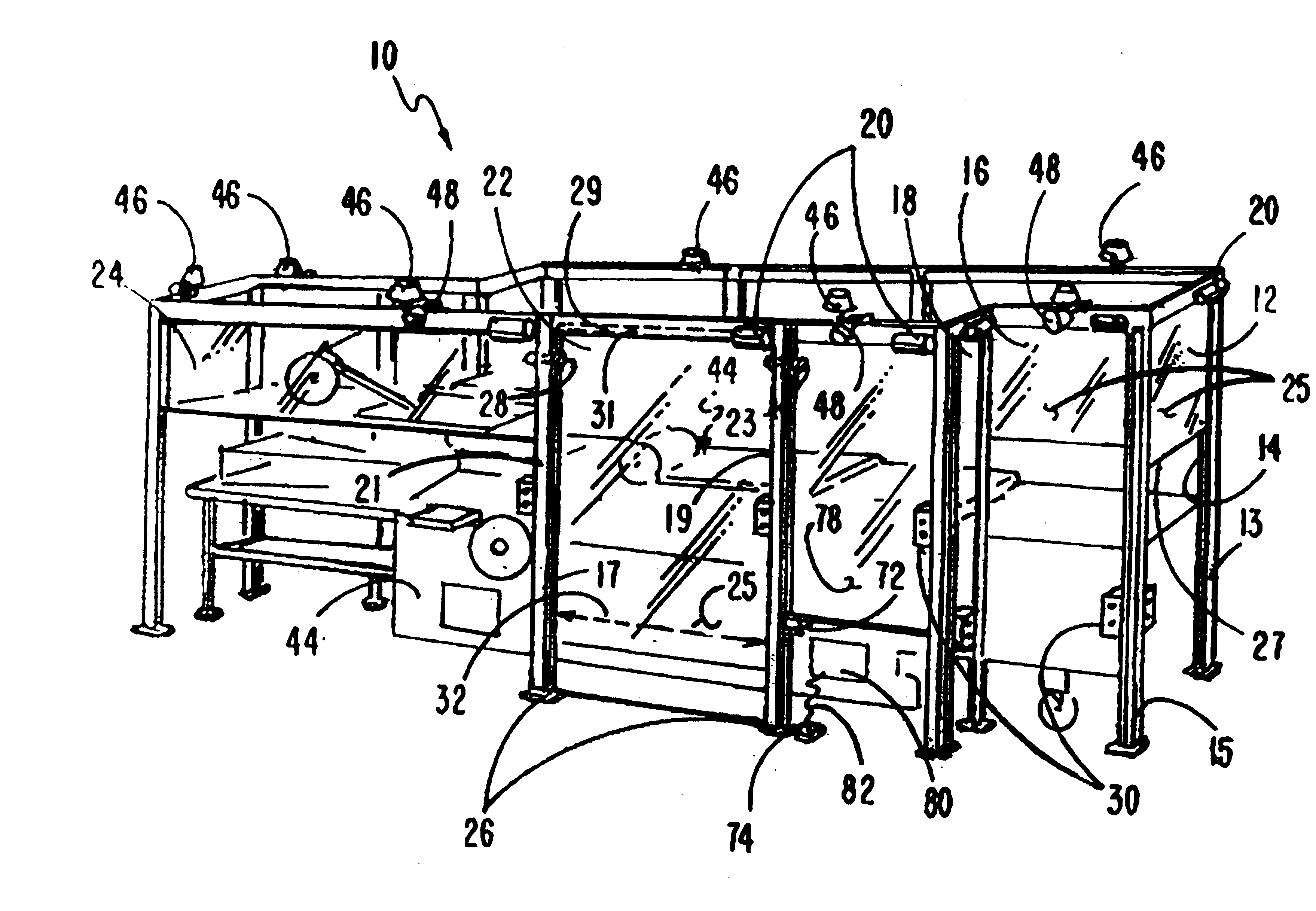
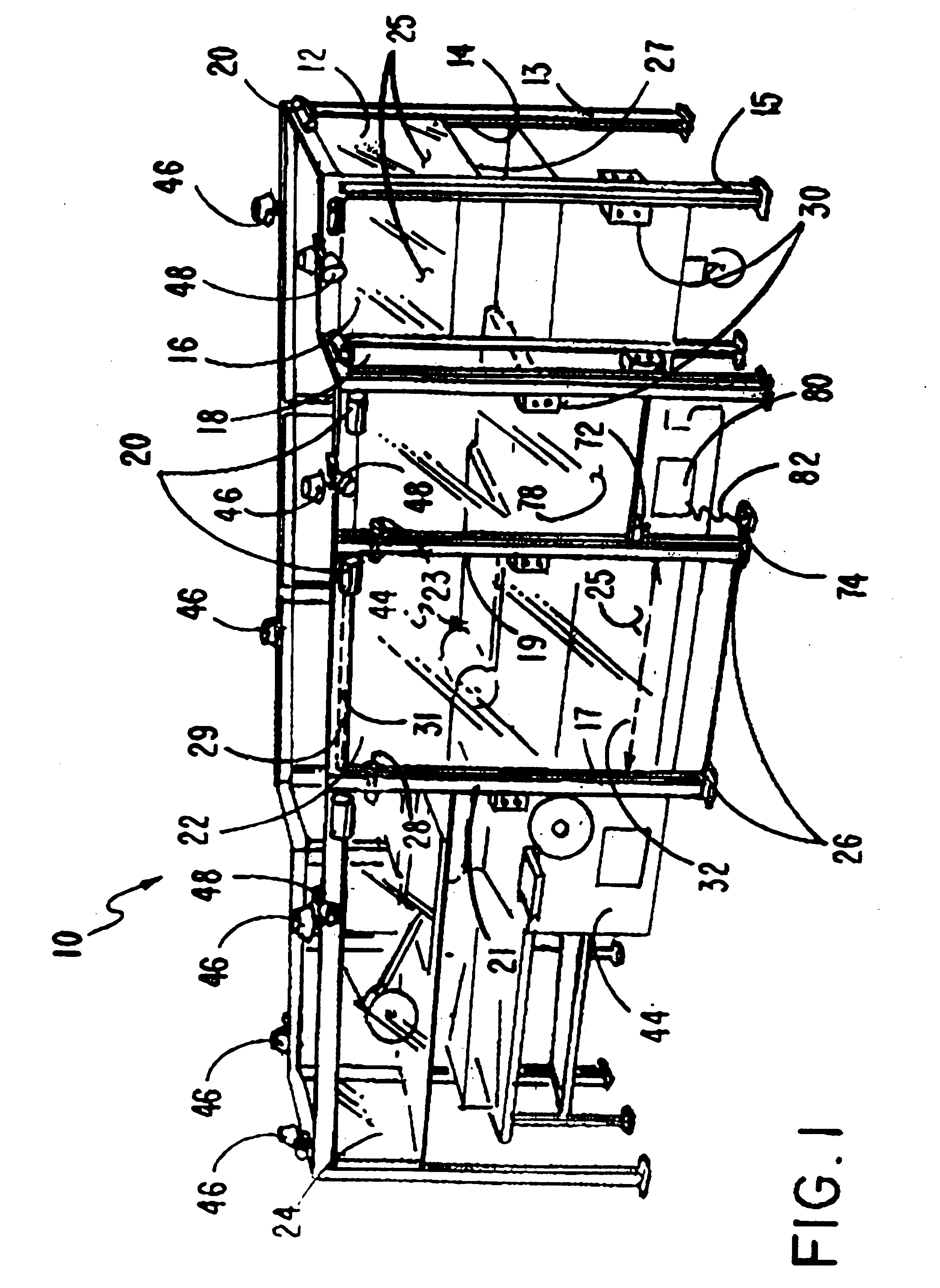
FIG. 1 illustrates the safety guard system 10 of this invention surrounding piece of machinery 44, shown in outline form. Safety guard system 10 is made up of a plurality of individual safety guard units, such as first safety guard unit 12, second safety guard unit 16, third safety guard unit 22 or fourth safety guard unit 24. These safety guard units are described with reference to one, but which description can be applied to each of the safety guard units. The safety guard units can be made of plastic, metal or other equivalent sturdy material in different widths and heights and positioned for use in various configurations to accommodate different shapes and sizes of machinery. Each safety guard unit, such as first safety guard unit 12, is comprised of first and second side track members 15 and 13 which are generally vertically disposed perpendicular to the floor. In one embodiment of the invention the side track members can be joined at their tops by an upper support member 31 to...


PUM


Abstract

A machine safety guard unit system having a flexible panel moved upwards and downwards between track members with the system positioned between the operative parts of a machine and a machine operator, such panel when closed protecting the machine operator and when moved upwards into its open mode, allowing access to the machine and preventing the machine from operating. In some embodiments more than one of such units can be disposed around a machine with alarm means; and in yet other embodiments, with interengagement means connecting such units.

Description

1. Field of the InventionThe device of this invention resides in the area of shields that are positioned between a machine operator and the operative parts of a machine and more particularly relates to a machine safety guard and system using a plurality of such machine safety guards, each of which can be positioned, and selectively opened or closed, in front of operative parts of a machine.2. Description of the Prior ArtIndustrial machinery can cause injuries to operators thereof if they are caught within the operative parts of the machinery or struck by elements emanating from such machinery. To reduce the chances of such injuries, the government through OSHA has instituted regulations which call for protective safety guards to cover certain operative parts of a machine to prevent a worker from being caught thereby or otherwise injured as the machine operates. These safety regulations provide for protective machine guards to be positioned in front of the operative parts of machiner...

Claims


Application Information

Patent Timeline
IPC IPC(8): F16P3/00F16P3/08
CPCF16P3/08Y10S52/14
Inventor DOHERTY, STEVEN G.
Owner RITE HITE HLDG CORP
Why Eureka
Try Eureka