Apparatus to control the dispersion and deposition of chopped fibrous strands

a technology of fibrous strands and apparatuses, which is applied in the field of apparatuses to control the dispersion and deposition of chopped fibrous strands, can solve the problems of added expense, problems of their own maintenance, and failure to achieve uniform fiber distribution on the collection surface, so as to prevent abrasive wear and reduce interference

Inactive Publication Date: 2001-12-04
OWENS CORNING COMPOSITE MATERIALS CANADA LP +1
View PDF25 Cites 7 Cited by
  • Summary
  • Abstract
  • Description
  • Claims
  • Application Information

AI Technical Summary

Benefits of technology

This need is met by the methods and apparatus of the present invention wherein an air amplifier and an outlet cone are associated with one another to form an air cannon which receives chopped fibers and forcefully deposits the chopped fibers on a collection surface or web moving beyond an outlet end of the outlet cone. The inner surface of the air amplifier is formed of an abrasion resistant material to prevent abrasive wear within the air amplifier. A binder is applied to the resulting mat of chopped fibers. The binder may be activated by the application of energy such as heat with the resulting treated mat being compacted, coole

Problems solved by technology

Unfortunately, static suppression equipment adds expense to equipment handling dry chopped fibers and can cause problems of its own in te

Method used


Image

  • Apparatus to control the dispersion and deposition of chopped fibrous strands
  • Apparatus to control the dispersion and deposition of chopped fibrous strands
  • Apparatus to control the dispersion and deposition of chopped fibrous strands

Examples


Embodiment Construction

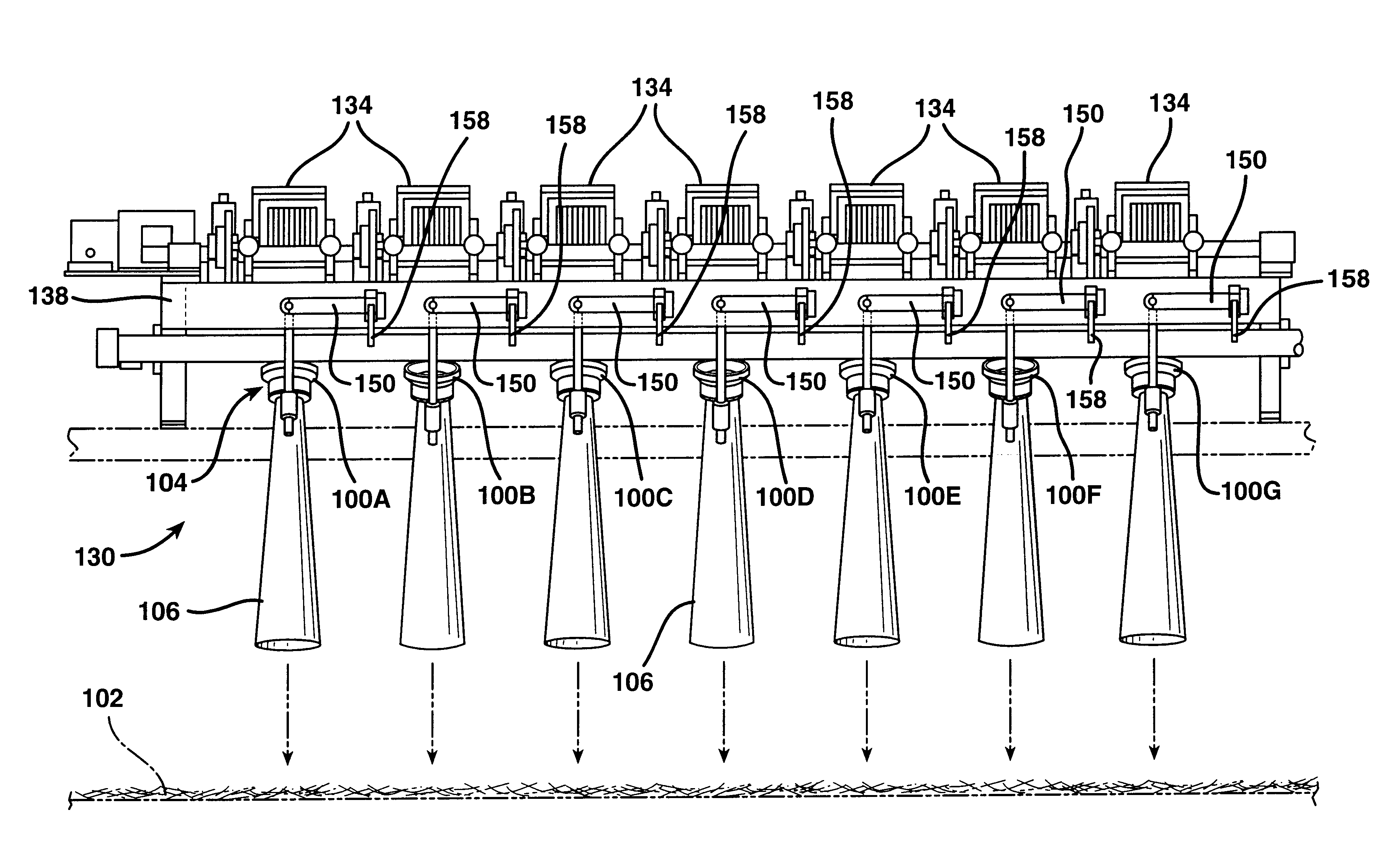
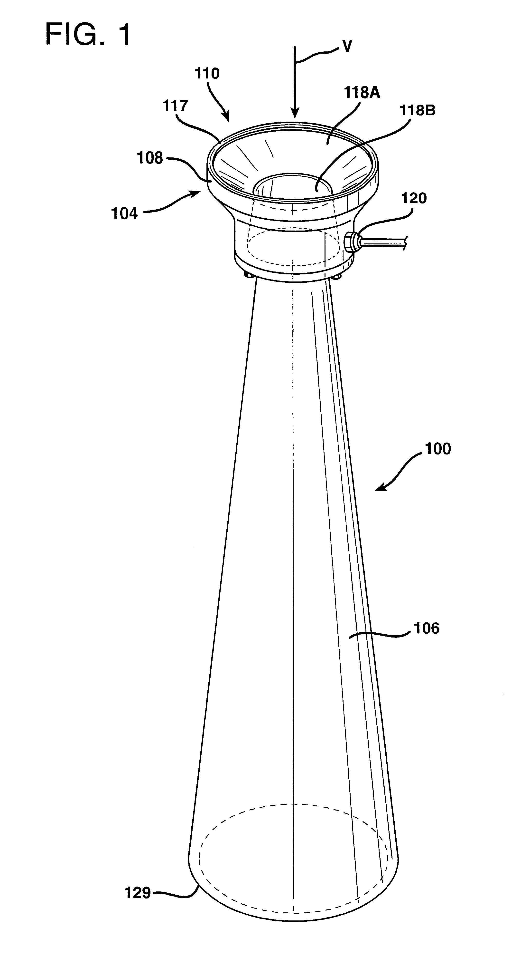
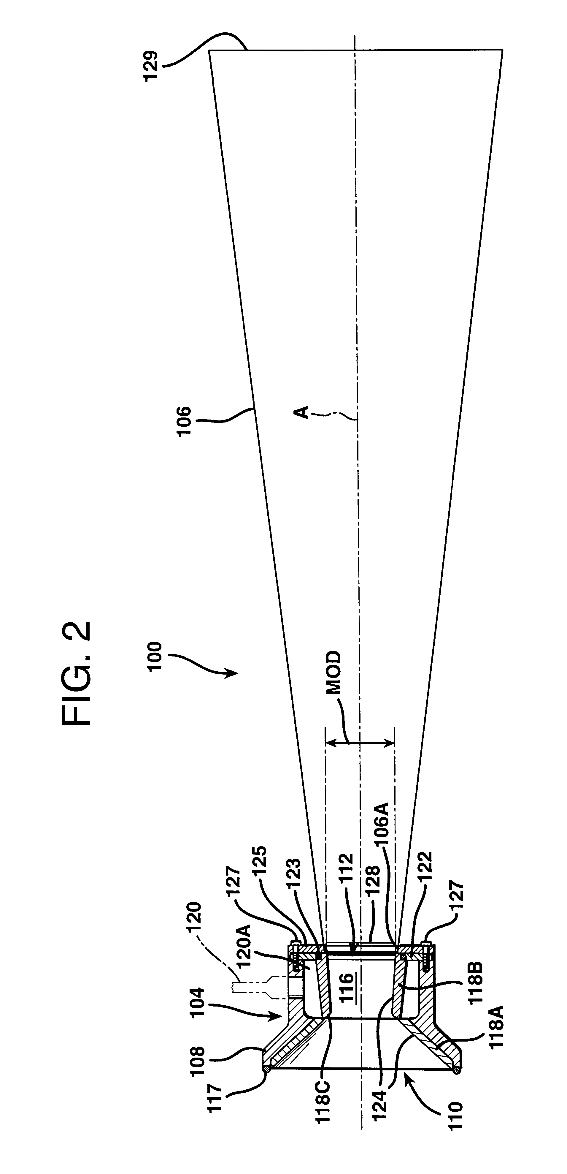
Reference will now be made to the drawings wherein FIGS. 1 and 2 illustrate an air cannon 100 which, alone or in banks of air cannons 100, collects chopped fibrous material, such as chopped glass fibers, and deposits received chopped fibers on a moving collection surface 102 as shown in FIGS. 3-5 and 9. The air cannon 100 comprises a pneumatically powered air amplifier 104 and a diffuser or outlet cone 106. Referring also to FIG. 2A, the air amplifier 104 comprises an inlet 110 located in plane X in FIG. 2A, an outlet 112 located in plane Y, and an inner section 114 which defines a passage 116 through the air amplifier 104 extending from the inlet 110 at plane X to the outlet 112 at plane Y. The air amplifier 104, in the embodiment illustrated in FIGS. 1, 2 and 2A, includes a shell 108 and insert structure 118 coupled to the shell 108.

Opposing ends of the shell 108 define the inlet 110 and the outlet 112 of the amplifier 104. The air amplifier 104 includes a bumper 117 secured to th...


PUM

PropertyMeasurementUnit
Thicknessaaaaaaaaaa
Thicknessaaaaaaaaaa
Thicknessaaaaaaaaaa

Abstract

An air cannon, formed by associating an air amplifier and an outlet cone with one another, receives chopped fibers and forcefully deposits the chopped fibers on a collection surface or web moving beyond an outlet end of the outlet cone. The air amplifier includes insert structure formed of an abrasion resistant material to prevent abrasive wear within the air amplifier caused by the chopped fibers. A binder is applied to the resulting mat of chopped fibers, the binder is activated by the application of energy with the resulting treated mat being compacted, cooled and rolled up to form a chopped strand mat package. For wide mats, one or more banks of air cannons extend across the moving collection web. The air cannons of each bank are alternately directed up-line and down-line of the web to reduce interference between the air cannons by means of L-shaped support rods which have generally horizontal and generally vertical legs which are separated from one another by acute and obtuse angles for up-line and down-line direction, respectively. The air cannons can also be individually adjusted to vary the aimed direction of the air cannons across the web by rotation of the generally horizontal legs of the L-shaped support rods. The air cannons forcefully direct chopped fibers to the web to overcome air turbulence within a forming hood and forces due to static electricity.

Description

The present invention relates in general to the dispersion and deposition of chopped fibrous materials and, more particularly, to apparatus for collecting chopped fibers from a source of such fibers and depositing the chopped fibers on a collection surface to be processed into non-woven webs of bonded chopped fibrous materials commonly referred to as chopped strand mat. While the invention is generally applicable to a wide variety of fibrous materials including mineral and organic fibrous materials, it will be described herein with reference to glass fibers for which it is particularly applicable and initially being applied.Continuous strands of fibrous material, such as glass filaments, have been collected and distributed using opposed Coanda effect surfaces to produce mats of such material used, for example, for insulation. Examples of such equipment are disclosed in U.S. Pat. Nos. 4,300,931; 4,466,819; and, 4,496,384. Such continuous strands typically are handled wet since they a...

Claims


Application Information

Patent Timeline
IPC IPC(8): C03B37/16C03B37/10D04H1/70
CPCC03B37/16D04H1/70D04H1/732C03B37/00
Inventor CLEMENTS, CHRISTOPHER J.HEISLER, DANIEL F.BERRY, KENNETH M.
Owner OWENS CORNING COMPOSITE MATERIALS CANADA LP
Why Eureka
Try Eureka