Automatic actuator system

a technology of automatic actuators and actuators, which is applied in the direction of service pipe systems, functional valve types, valve operating means/releasing devices, etc., can solve the problems of increased piping, wiring, cost, and increased complexity of the carsten system, and achieves the effect of reducing the risk of actuation failure, and reducing the safety of the system

Inactive Publication Date: 2001-12-11
WHITMORE BRIAN SCOTT SR
View PDF6 Cites 19 Cited by
  • Summary
  • Abstract
  • Description
  • Claims
  • Application Information

AI Technical Summary

Benefits of technology

b. operating said actuator on said cylinder where said cylinder has one or more of the items selected from the group consisting of the items listed in step a) above.
The stem is operatively connected to a motor withi

Problems solved by technology

As these became more and more complex, there developed a tendency to place various parts of the systems in positions remote to the actual storage cylinders themselves.
In some cases certain advantages were realized, but often at the cost of more extensive wiring and piping which in some cases gives rise to safety problems
The Carsten system is extensive in its undertakings and complex in its details.
This requirement gives rise to added piping, wiring, expense and may give rise to safety concerns.
Many chemicals such as chlorine, sulfur dioxide, ammonia and the like may be hazardous or toxic materials, at least under certain circumstances and by certain definitions.
The containers are themselves typically left unatten

Method used


Image

  • Automatic actuator system
  • Automatic actuator system
  • Automatic actuator system

Examples


Embodiment Construction

To place the present invention in its usual context and environment, it is necessary to review briefly several prior art items.

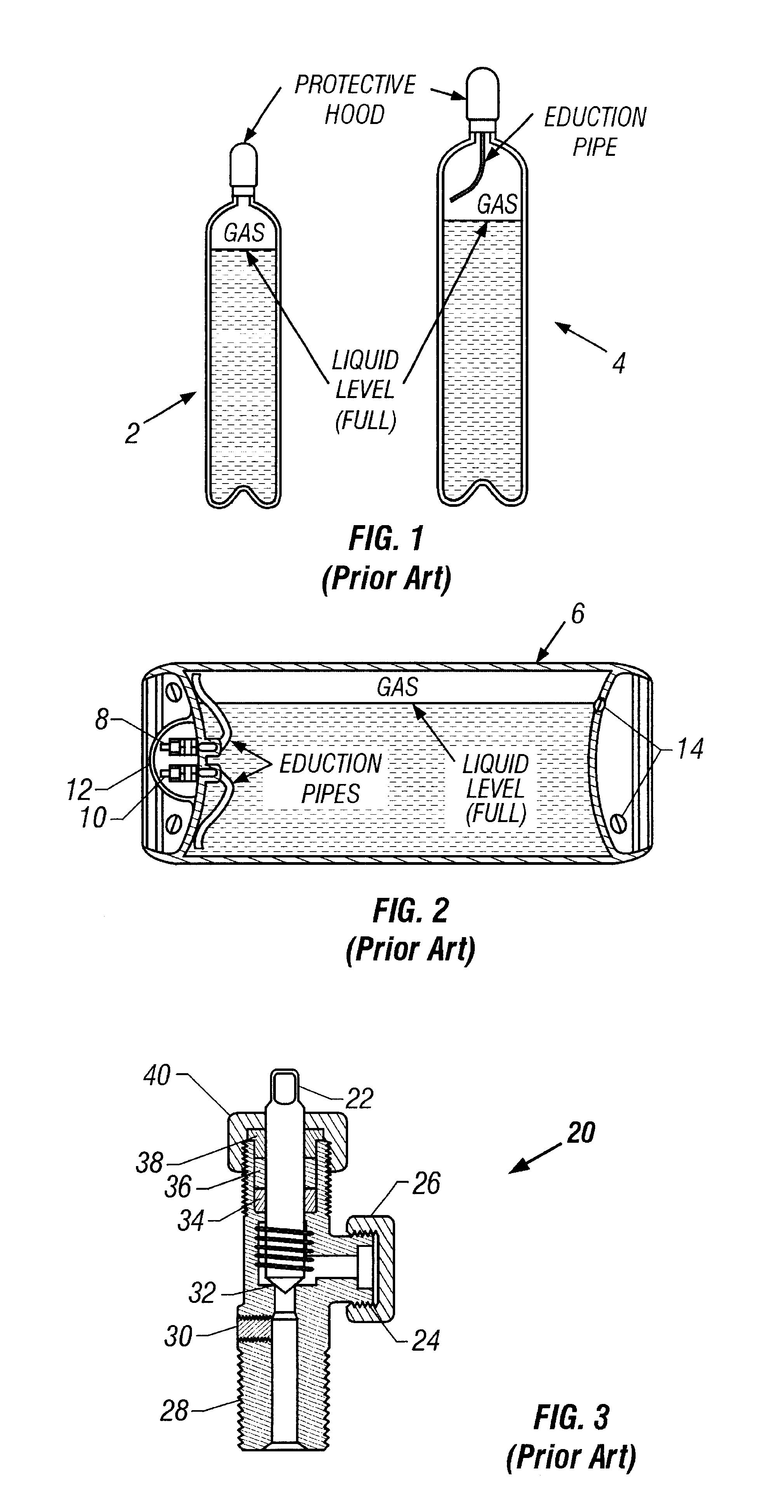
As shown in FIG. 1, we see a cross-sectional view of 150 pound cylinders for chlorine 2 or sulfur and for ammonia 4. Cylinders such as these are typical of the smaller cylinders to which the present invention is applied.

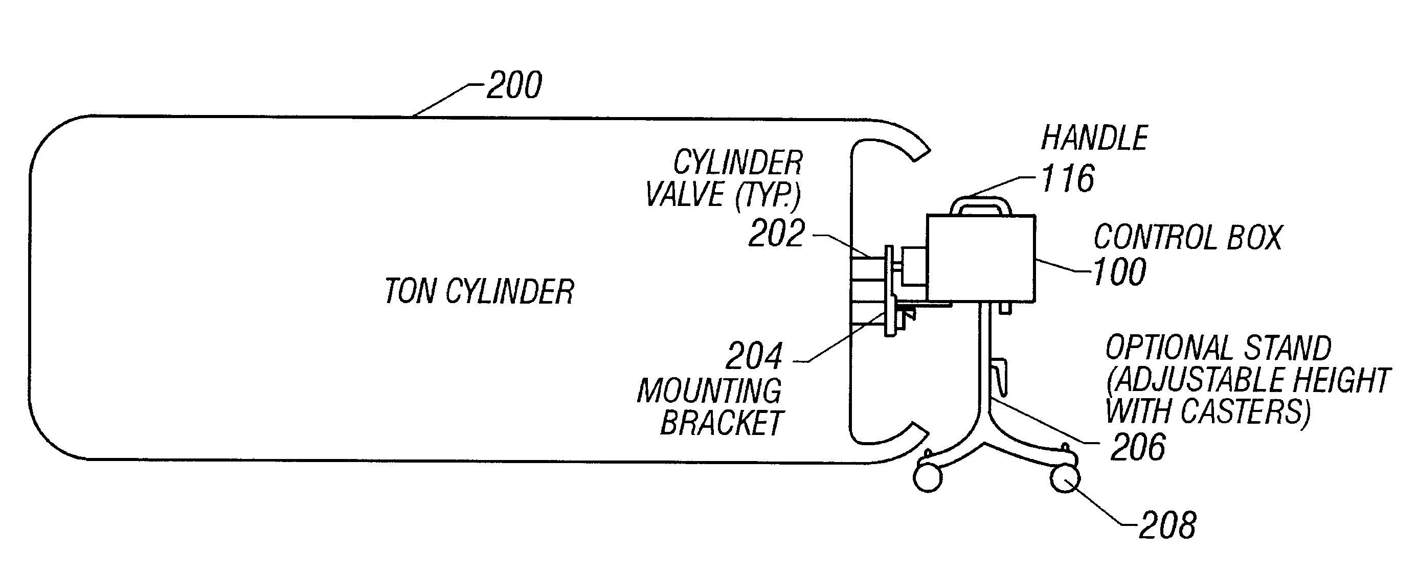
The larger size cylinders to which the present invention may be applied are shown in the typical "Ton" container of FIG. 2 which might be used for chlorine or sulfur dioxide.

As shown in FIG. 2, the "Ton" container 6 is placed in a horizontal position with the upper valve 8 and the lower valve 10 in a vertical line, one above the other, with the upper valve 8 on top. The valves 8 and 10 may be protected by a protective hood 12.

In this position, gas is discharged when the upper valve 8 is open. Liquid is discharged when the lower valve 10 is open. These options are made possible by the eduction tubes or pipes shown in FIG. 2 which extend from e...


PUM


Abstract

A system for filing or discharging compressed gas or liquid cylinders mounted on the cylinder. An automatic system for filing or discharging a compressed gas cylinder, specifically chlorine, sulfur dioxide, or ammonia cylinders. The system includes an electric motor that rotates the cylinder valve system toward open or closed position without interfering with or requiring additional adapters for the filing or discharge hardware. The motor, gears, and controls are assembled as one unit to eliminate the necessity for a separate control panel or interconnecting control wires. The system has the capabilities for integral leak detection with automatic shutdown, battery backup in the event of power failure, remote control by leak detector, remote control panic button, remote low weight transmitter, remote vacuum switch for automatic switch-over systems and other remote digital signals. The system requires only a flexible power cord for trickle charge of the battery backup, which makes the assembly totally portable when not in use. Placement of the system container can be accomplished by connection to the cylinder valve, a permanent stand, or a movable stand on casters. Motor and controls are accomplished through an on-board microprocessor with integral LED displays for "C<SMALLCAPS>LOSED</SMALLCAPS>," "A<SMALLCAPS>LIGN</SMALLCAPS>," and "O<SMALLCAPS>PEN</SMALLCAPS>" indicators. Programming is accomplished through an integral keypad. Actual valve position is transmitted to the microprocessor from a direct-coupled potentiometer.

Description

The present invention relates to the charging or discharging of compressed fluid cylinders.Various systems have been developed over the years to fill or discharge gas or liquid cylinders. As these became more and more complex, there developed a tendency to place various parts of the systems in positions remote to the actual storage cylinders themselves. In some cases certain advantages were realized, but often at the cost of more extensive wiring and piping which in some cases gives rise to safety problemsThe physical arrangement of the various systems has also been a factor tending to disperse the systemThe prior art includes many such systems, including the following:U.S. Pat. No. 5,588,637, Carsten;U.S. Pat. No. 4,220,313 to Peterson, et al.;U.S. Pat. No. 4,541,609 to Smith;U.S. Pat. No. 4,647,007 to Bajka;U.S. Pat. No. 4,754,949 to Fukamachi;U.S. Pat. No. 4,790,514 to Marks; andU.S. Pat. No. 4,845,416 to Scholl, et al.The above-noted Carsten patent is a good example of one such ...

Claims


Application Information

Patent Timeline
IPC IPC(8): F16K31/04F16K37/00F16K1/00F16K1/30
CPCF16K1/30F16K31/047F16K37/0041Y10T137/0486Y10T137/8242Y10T137/5762
Inventor SLAYDON, GARY
Owner WHITMORE BRIAN SCOTT SR
Why Eureka
Try Eureka