Global time calculator

a calculator and global technology, applied in the field of time calculating equipment, can solve the problems of high cost, complicated device use, and inconvenient personal us

Inactive Publication Date: 2001-12-18
WHALEN EDWARD E
View PDF24 Cites 6 Cited by
  • Summary
  • Abstract
  • Description
  • Claims
  • Application Information

AI Technical Summary

Problems solved by technology

This, however, is costly, and each clock must be calibrated from time to time.
However, this approach is usually not convenient for personal use since electronic devices are generally voluminous, expensive and/or cumbersome and sometimes even impossible to be transported from place to place.
However, this device is complicated to employ as it requires the user to have significant and specific geographical awareness and perform a complicated series of manipulations to determine the time in a specific country in a geographic region.
Such manipulations render the device inefficient and generically impractical to use.
However, this device is also complicated to use, requiring one to choose a relative geographic location and perform a series of adjustments to the device to calculate the time difference.
However, due to its design, only a small number of localities can be displayed on its face, limiting its use.
Furthermore, such a device is particularly cumbersome and not easily carried on one's person.
However, due to its structure, this device is limited in the number of localities which can be displayed.
Furthermore, its design requires synchronization of its electrical elements, which can fail, rendering the device useless.
Moreover, the use of e

Method used


Image

  • Global time calculator
  • Global time calculator
  • Global time calculator

Examples


sixth embodiment

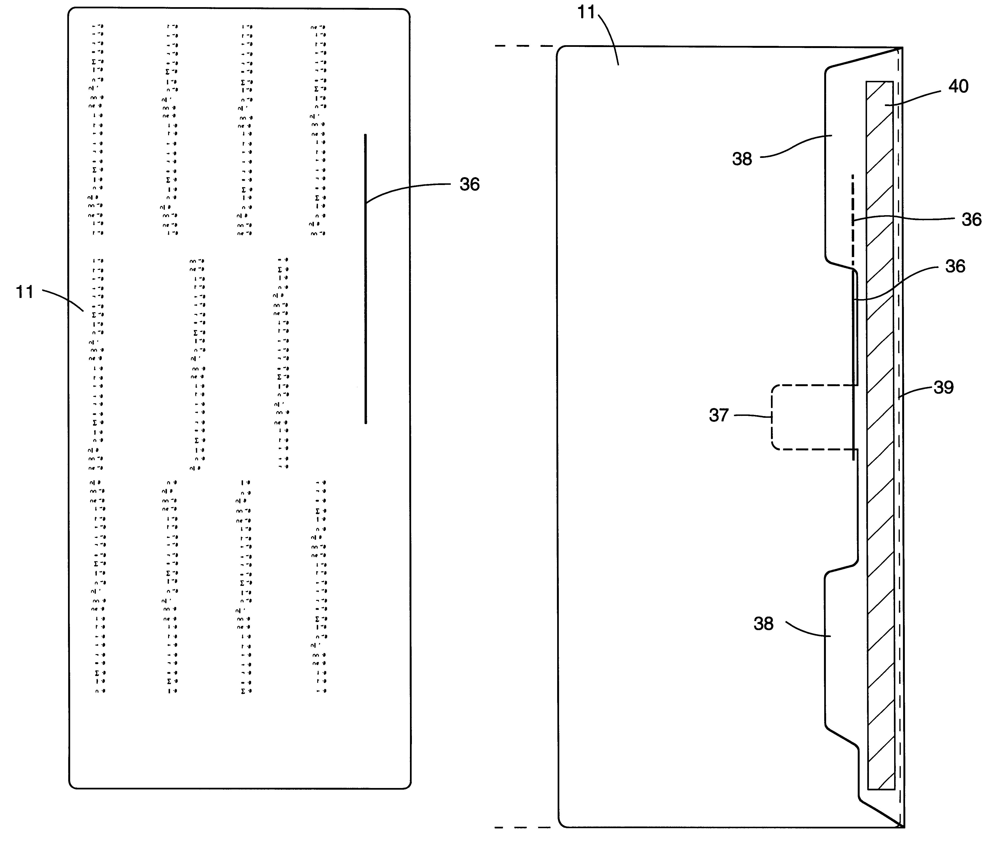
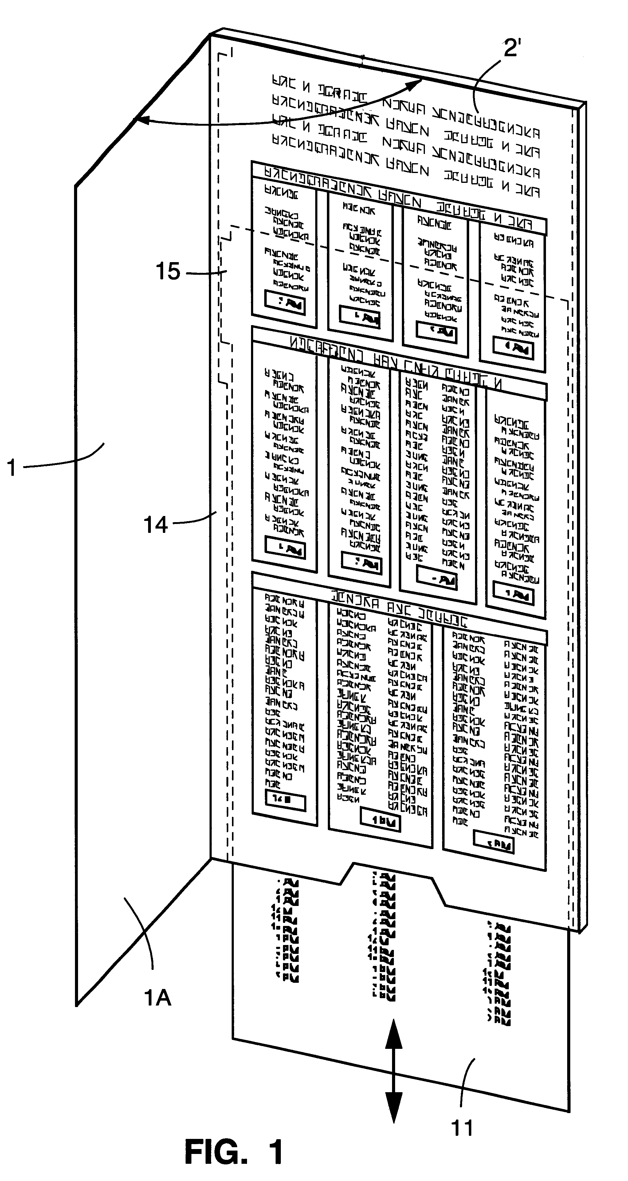
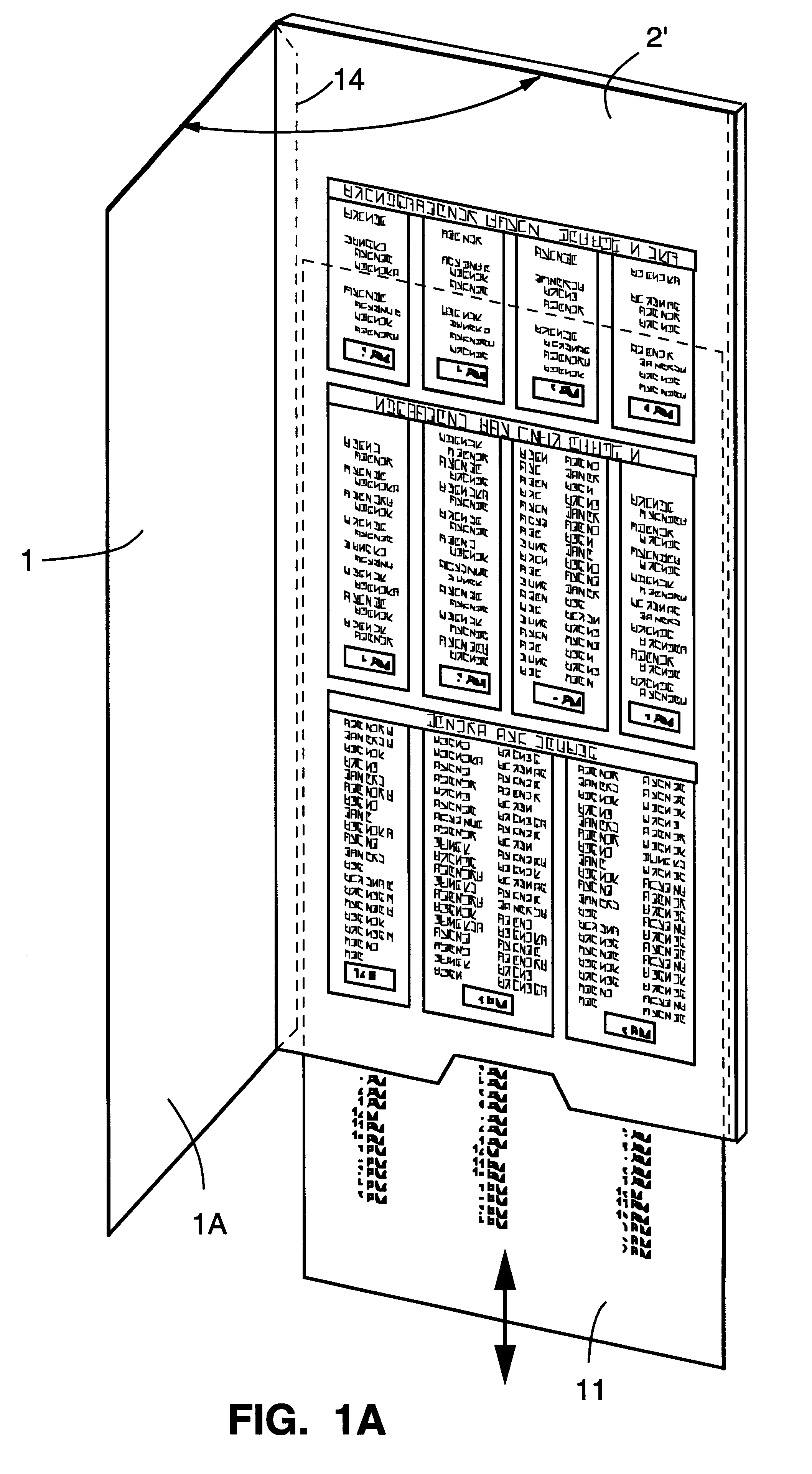
With reference now to FIGS. 16A, 16B, 16C, and 16D, a sixth embodiment and method of manufacturing the invention is described. There are two inter-related friction fits in this method of manufacturing: (1) Friction Fit A and (2) Friction Fit B. Friction Fit A is created by the following: (1) the contact between the edges of the sliding insert 11 and the scoring 35 within the sleeve 2' created by pages 2 and 3; and (2) the contact between the sliding insert facings and the inside facings of the sleeve 2' and the glue flap facing.

Friction Fit B is created by the following: (1) the contact between the edges of the die cut slit 36 in the sliding insert 11 and the facing of the tongue 37; (2) the contact between the inside facing of the sleeve 2' and the facing of the tongue 37; and (3) the fulcrum effect created by the insertion of the tongue 37 into the sliding insert 11. The sliding insert 11 rides freely on the glue flap extensions 38, but the tongue 37, when inserted into the die cu...

second embodiment

As illustrated in FIGS. 14B and 15B, a left side positioned stop mechanism consists of a 2.6 inch by 1 / 4 inch rectangular die cut 28' may be positioned at the left midpoint of insert 11 approximately 3 inches from the top margin and approximately 1 / 4 inch from the left margin. As illustrated in FIG. 13B, the grommet hole 27 is positioned approximately 6 inches from the top margin and also 1 / 4 inch from the left margin. The grommet 26 is then inserted through the page 2 grommet hole 27, the rectangular die cut 28' of insert 11 and the page 3 grommet hole 27. In this embodiment, the grommet placement is at the bottom of the 2.6 inch rectangular die cut 28' on insert 11 to allow the insert adequate slide room.

third embodiment

As illustrated in FIGS. 14C and 15C, a left side positioned stop mechanism consists of a 2.6 inch by 1 / 4inch rectangular die cut 28' at the bottom left of insert 11, approximately 9 inches from the top margin and approximately 1 / 4inch from the left margin. The grommet hole 27, as illustrated in FIG. 13C, is placed approximately 9 inches from the top margin and also 1 / 4 inch from the left margin. The grommet 26 is then inserted through the page 2 round die cut hole, the 2.6 inch rectangular die cut 28' and the page 3 grommet hole 27. In this embodiment, the grommet placement is at the bottom of the 2.6 inch rectangular die cut 28' on the insert to allow insert 11 adequate slide room.

Alternatively, the rectangular die cut 28' on insert 11, the grommet 26 and grommet hole 27 may be positioned on the right side of the calculator as shown in FIGS. 14G, 14H and 14I. In further detail, and as illustrated in FIGS. 14C and 15D, a 2.6 inch by 1 / 4 inch rectangular die cut 28' is positioned at ...


PUM


Abstract

A global time calculator includes an insert and a sleeve. The insert is marked on both its sides (or on a single page slide insert on one side) with vertical columns of incremental time designations, and may or may not contain a stop mechanism. The insert is slidable and connected with the sleeve so as to be shiftable in a vertical direction. Both sides of the sleeve (or in some embodiments a single side of the sleeve) have areas for obscuring vertically aligned time designations that are in excess of unobscured time designations.

Description

1. Field of the InventionThe present invention relates to a time calculating apparatus, and more particularly to a sliding type apparatus that enables one to quickly and simultaneously display corresponding local standard time in all of the countries of the world, a number of overseas dependencies of various countries, and a large number of cities throughout the world.2. Notice of CopyrightA portion of the disclosure of this patent document contains material which is subject to copyright protection. The copyright owner has no objection to the facsimile reproduction by anyone of the patent document or the patent disclosure, as it appears in the Patent and Trademark Office patent file or records, but otherwise reserves all copyright rights whatsoever.3. Description of the Related ArtAs is well known, with the increasing use of intercontinental world travel, particularly with supersonic transportation being available, and the various telecommunications systems around the world, the dif...

Claims


Application Information

Patent Timeline
IPC IPC(8): B42D15/00G09B29/14G06C3/00
CPCB42D15/00G09B29/14G09F11/00
Inventor WHALEN, EDWARD E.
Owner WHALEN EDWARD E
Why Eureka
Try Eureka