Grade-holding brake system
- Summary
- Abstract
- Description
- Claims
- Application Information
AI Technical Summary
Problems solved by technology
Method used
Image
Examples
first embodiment
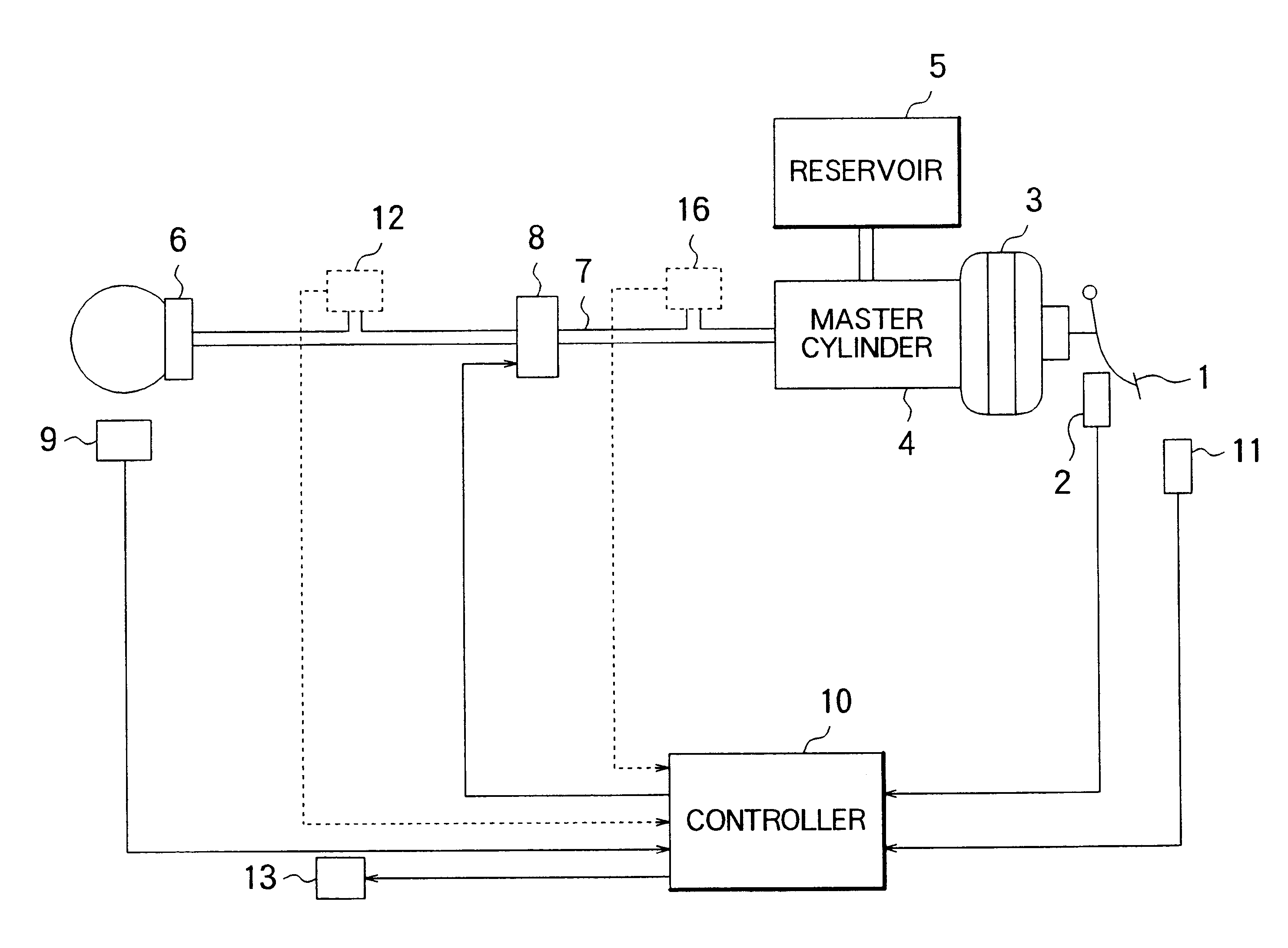
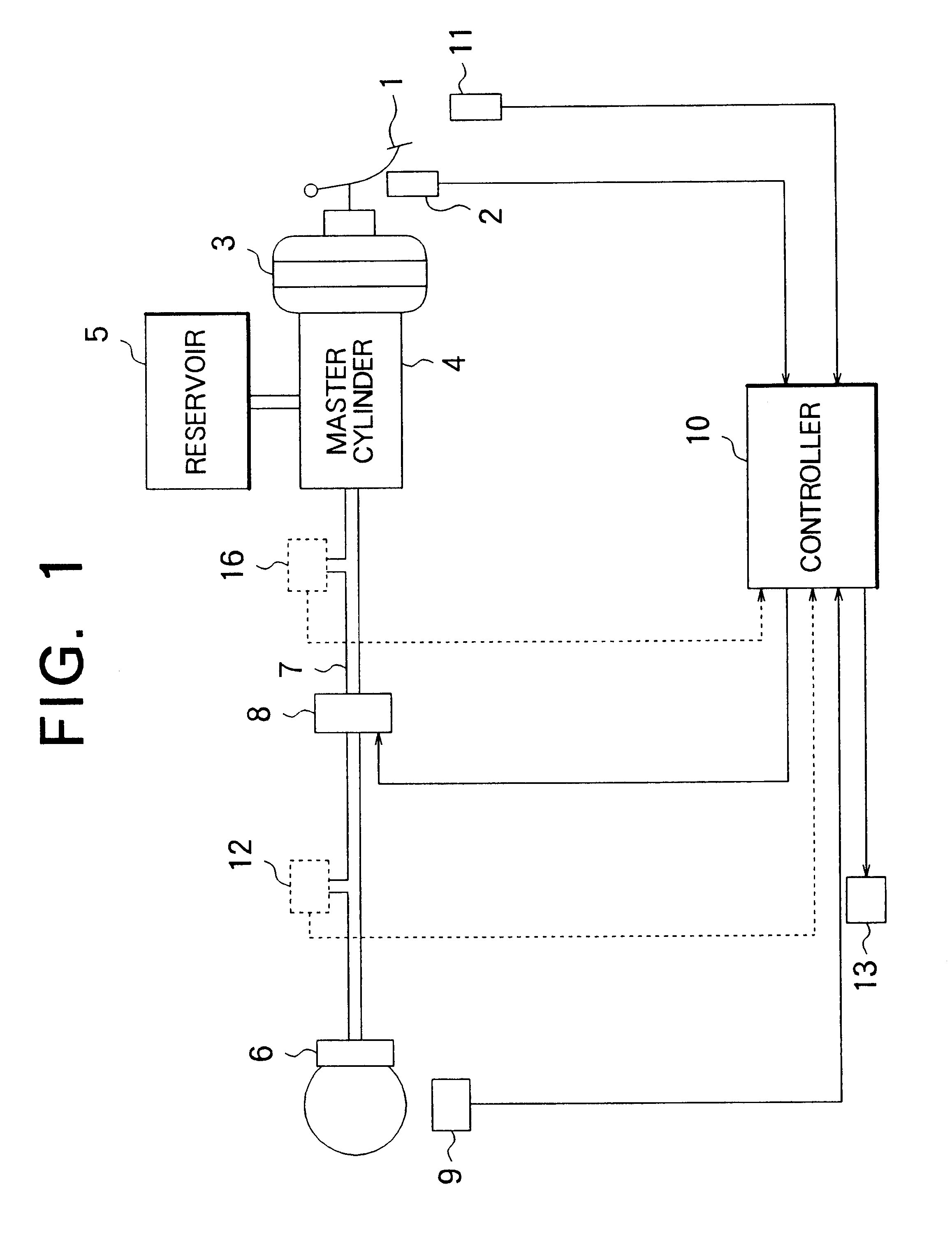
FIG. 1 is a schematic view showing a structure of a grade-holding brake system in accordance with the present invention.
In FIG. 1, a master cylinder 4 is connected to a brake pedal 1 through a booster device 3 for feeding brake oil contained in a reservoir 5 to brake tubing 7 by operating the brake pedal 1. A wheel cylinder 6 is used to increase pressure of the brake oil so that a braking force may be applied to a wheel.
A cut-off valve 8 (first cut-off valve) as pressure controlling means is provided in the brake tubing 7 for connecting an outlet port of the master cylinder 4 to the wheel cylinder 6. The cut-off valve 8 is electrically connected to and opened and closed by a controller 10. However, the cutoff valve 8 is kept in an open condition unless a command is received.
A brake switch 2 detects that the brake pedal 1 has been depressed to a predetermined depth. An accelerator switch 11 detects that an accelerator pedal (not shown) has been depressed to a predetermined depth. A v...
embodiment 2
FIG. 8 is a schematic view showing a structure of the grade-holding brake system according to a second embodiment of the present invention.
As shown in FIG. 8, a master cylinder 4 for feeding brake oil contained in a reservoir 5 to a brake tubing 7a by operating a brake pedal 1 is connected to the brake pedal 1 through a booster device 3. A wheel cylinder 6 is used to increase pressure of the brake oil so that a braking force may be applied to each wheel. The brake tubing 7a is connected to an outlet port of the master cylinder 4. This brake tubing 7a is branched into two branch tubings 7b and 7c.
The branch tubing 7b is connected to the wheel cylinder 6 through a cut-off valve 8. The branch tubing 7c is connected to the wheel cylinder 6 through a pressure booster valve 14 and a pressure booster pump 15. Further, the cut-off valve 8 and the pressure booster valve 14 are electrically connected to a controller 10 and are opened and closed by the controller 10.
The cut-off valve 8 as a fi...
embodiment 3
FIG. 14 is a flowchart showing a portion of a control program for the grade-holding brake system according to a third embodiment of this invention.
The grade-holding brake system according to the third embodiment to change the control processing contents of step 202 (input process) and step 203 (control condition process) in the first embodiment (see FIG. 2).
Further, since the content of the input process according to the third embodiment is substantially the same as the process content (see FIG. 10) of the second embodiment, the explanation thereof will be omitted.
A flowchart of the control condition determination shown in FIG. 14 will now be described. Further, Ztimer, described later, is a RAM for temporarily storing the calculation result. Also, XPtarget and Xtime are data stored in the ROM before the execution of the program.
As shown in FIG. 14, first, in step 1501, it is determined whether or not the accelerator switch 11 is in the ON condition (accelerator pedal depressed cond...
PUM
 Abstract
Description
Claims
Application Information
 - R&D
- Intellectual Property
- Life Sciences
- Materials
- Tech Scout
- Unparalleled Data Quality
- Higher Quality Content
- 60% Fewer Hallucinations
Browse by: Latest US Patents, China's latest patents, Technical Efficacy Thesaurus, Application Domain, Technology Topic, Popular Technical Reports.
© 2025 PatSnap. All rights reserved.Legal|Privacy policy|Modern Slavery Act Transparency Statement|Sitemap|About US| Contact US: help@patsnap.com


