Vibration actuated traffic monitoring system

a technology of vibration-actuated traffic and monitoring system, which is applied in the direction of traffic movement detection, traffic signal control, instruments, etc., can solve the problems of high cost and inconvenience, high cost and cost prohibitive to install such a system at an intersection, and achieve easy and inexpensive implementation, installation and movement, and promotion of lane discrimination and recognition

Inactive Publication Date: 2001-12-25
MEE GARY L +1
View PDF13 Cites 20 Cited by
  • Summary
  • Abstract
  • Description
  • Claims
  • Application Information

AI Technical Summary

Benefits of technology

In a specific embodiment, the vibration generator comprises at least one channel or groove in the traffic bearing surface. Preferably, each of the grooves or channels extends across the traffic-bearing surface substantially perpendicular to the flow of traffic. The number of channels or grooves and the pattern of spacing between channels or grooves may be used to distinguish the vibration pattern, thus fostering lane discrimination and recognition. The specific dimension and geometry of each of the grooves or channels may also be used to generate distinct vibrations to further distinguish vibration patterns. This embodiment is advantageous in that it can be easily and inexpensively implemented. For example, instead of requiring days of excavation and resurfacing of the traffic bearing surface to implant a sensor, grooves or channels can be "cut" into the traffic bearing surface quickly and easily using a conventional concrete cutter. Alternatively, the vibration generator may include raised strips, bumps, or cables stretched perpendicularly across the traffic-bearing surface. The grooves, channels, strips, bumps, or cables may also emanate distinct vibrations recognizable to the geophone according to their number, spacing, geometry, and dimensions.
In a preferred embodiment, the vibration receiver comprises a geophone, which is preferably positioned proximate the traffic-bearing surface, e.g., partially buried in the ground next to the roadside. Since the vibration receiver is not physically connected to the vibration generator, it can be installed and moved with little expense or difficulty. This is unlike other systems where sensors are imbedded in the traffic-bearing surface, thus requiring expensive and time consuming excavation to salvage monitoring system components or to move the monitoring system to a new location. Further, unlike other systems, repairs of the vibration receiver can be easily performed without tearing up the traffic bearing surface. Thus, this embodiment is advantageous in that it still maintains the superiority of controlling traffic flow based on the actual traffic in the area and avoids the cost prohibitive, installation, excavation and maintenance of other systems.

Problems solved by technology

They are costly and inconvenient since the road surface must be excavated in order to implant the sensors.
For example, it is not unusual for mere sensor installation of such an embedded system to be highly expensive, which is, of course, borne by the taxpayer.
Consequently, it may be cost prohibitive to install such system at an intersection.
Further, since the actuating elements, e.g., the inductive loops, are physically connected to the processor and controller of the traffic light system, these systems are, for the most part, permanent, thus preventing easy removal and implementation at another location.

Method used


Image

  • Vibration actuated traffic monitoring system
  • Vibration actuated traffic monitoring system
  • Vibration actuated traffic monitoring system

Examples


Embodiment Construction

Specific embodiments of the invention will now be described as part of the detailed description. In the drawings, like elements have the same reference numbers for purposes of simplicity. It is understood that the invention is not limited to the specific examples and embodiments, including those shown in the drawings, which are intended only to assist a person skilled in the art in practicing the invention. Many modifications and improvements may be made without departing from the scope of the invention, which should be determined based on the claims below, including any equivalents thereof.

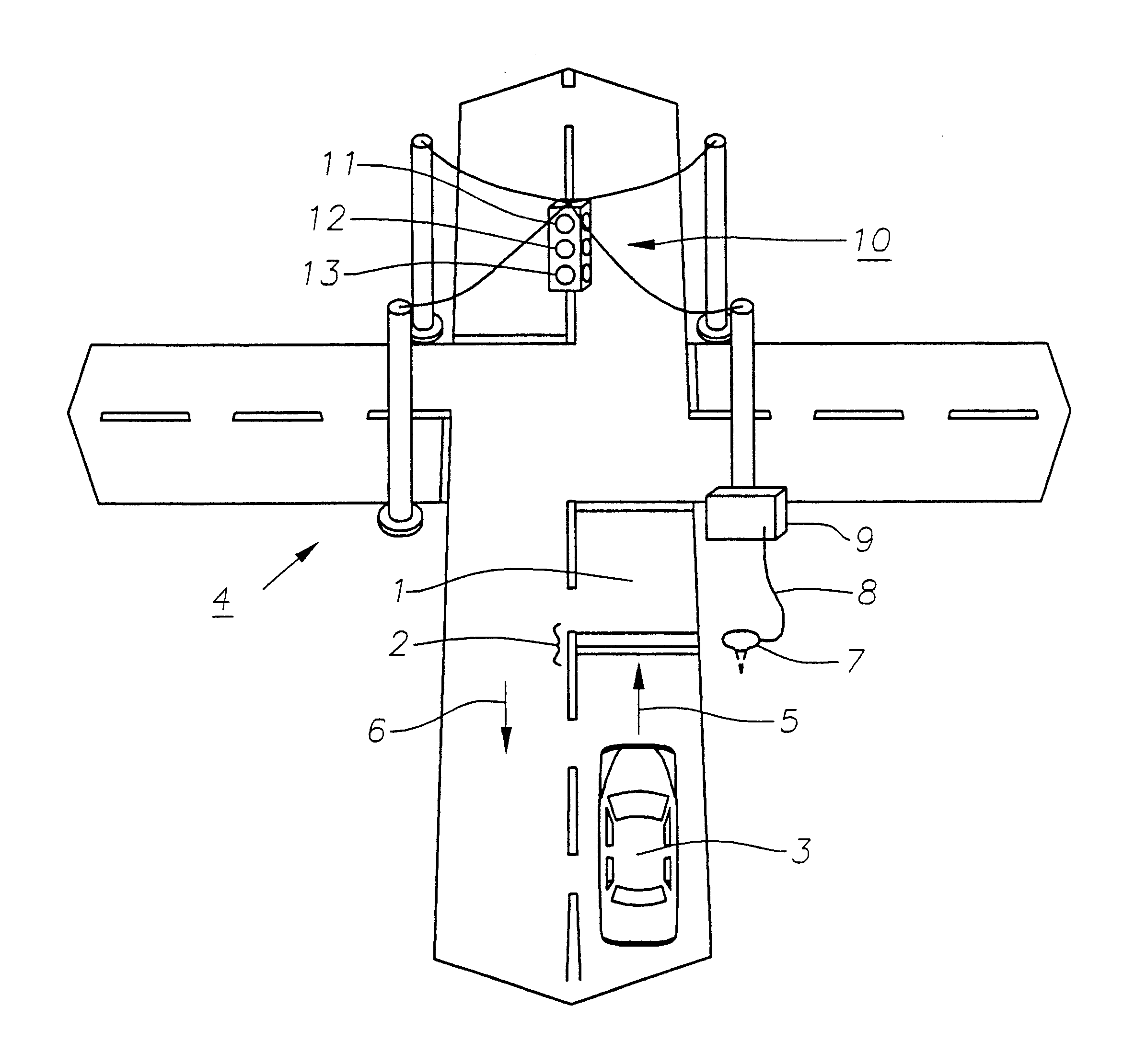
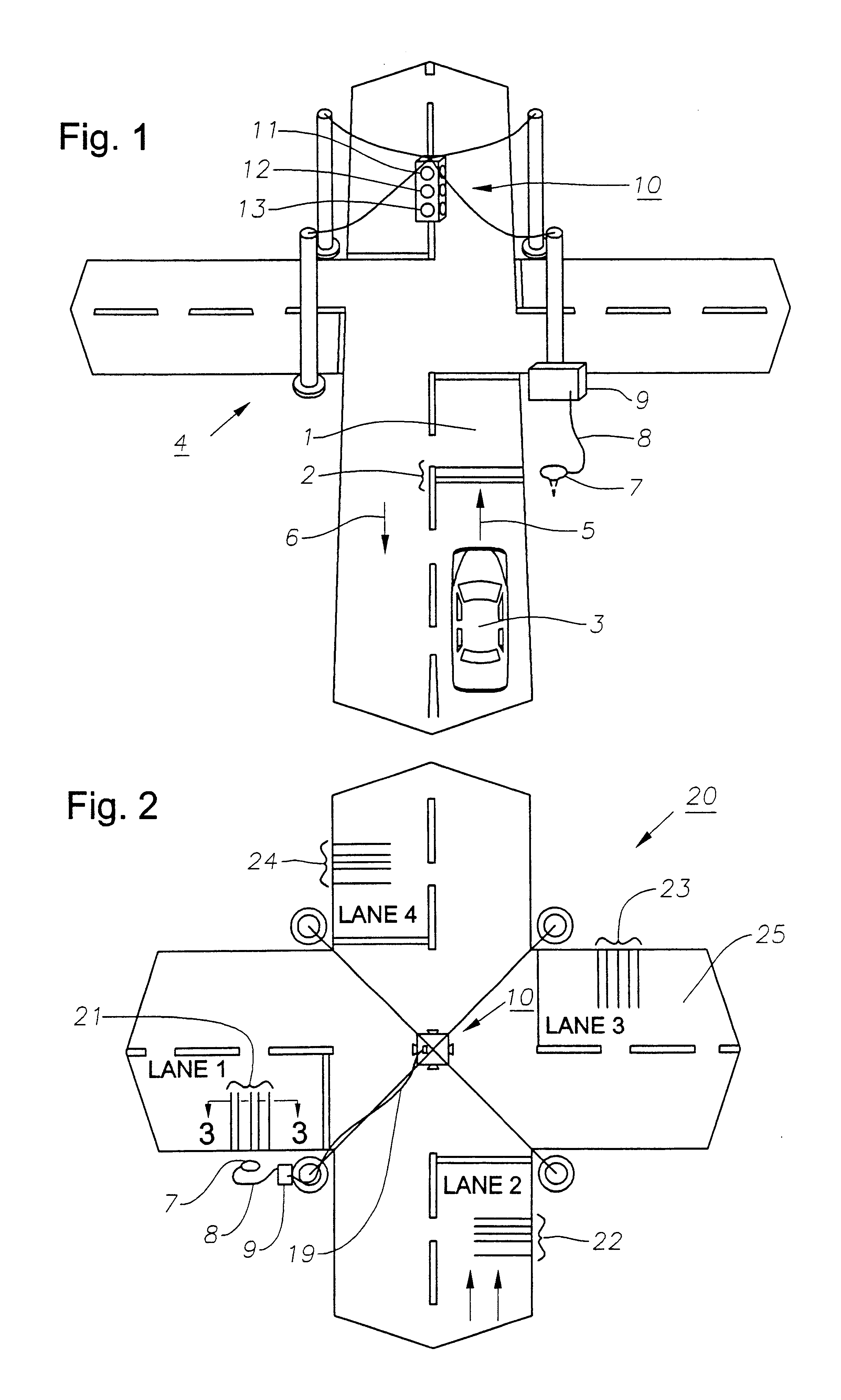
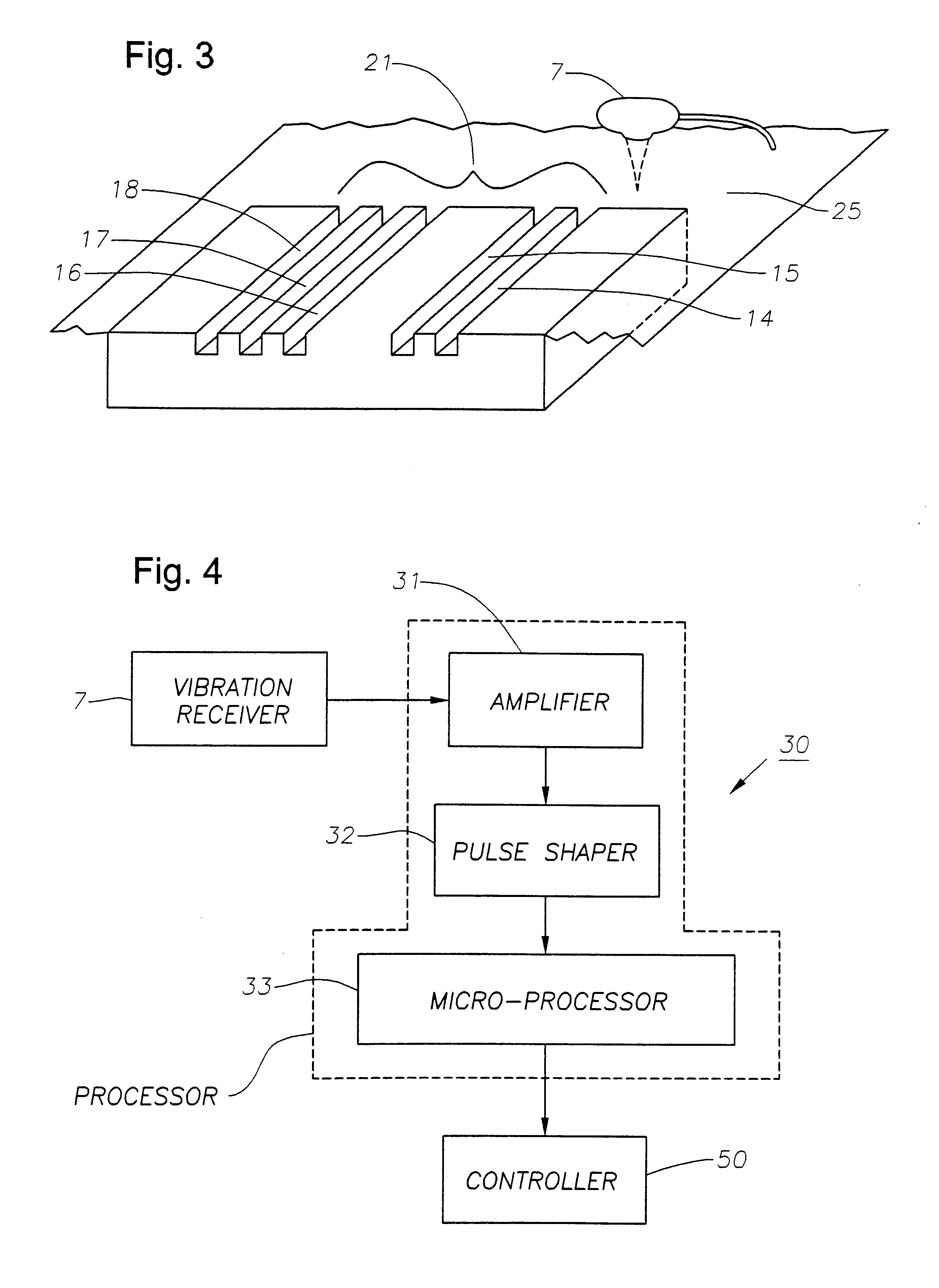
In a broad aspect, this invention relates to traffic monitoring. In a specific embodiment, the invention is directed to a method and apparatus for accurately controlling a traffic light 10 at traffic intersection 4, preferably upon receipt or recognition of a pattern of vibrations produced by the passing of vehicle 3 over a vibration generator 2, as shown in FIG. 1. The pattern of vibrations corr...


PUM


Abstract

A device for controlling a traffic light, where the controlling of the traffic light is dependent upon receipt and recognition of vibrations. The device includes a vibration receiver for detecting vibrations transmitted through the ground, a processor for converting one or more of the vibrations into a control signal and a controller to trigger a traffic light in response to the control signal. The device may also include a vibration generator, e.g., at least one channel or groove in a traffic-bearing surface. The vibration generator preferably facilitates the production of a pattern of vibrations when the tire of a vehicle passes over the vibration generator. Further, the device may include a vibration receiver, capable of detecting a pattern of vibrations and producing a pattern of signals corresponding to said pattern of vibrations.

Description

1. Field Of The InventionBroadly, this invention relates to traffic monitoring and in a specific embodiment to a system for controlling traffic lights at traffic intersections by detecting and processing vibrations actuated by a vehicle passing over a vibration generator. In another specific embodiment, the invention relates to a system which utilizes a vibration receiver to detect vibrations and a processor to convert the vibrations into a control signal which triggers traffic lights.2. Description Of Related ArtA well-known fixture at traffic intersections is the common "traffic light," which traditionally has three "light elements," red, yellow, and green. Traffic lights are typically used to prevent collisions at intersections, to determine which vehicle has the right-of-way, and to control traffic flow.Many, if not most, traffic intersections have a predetermined timing mechanism that sets a time for the traffic light's green light element, yellow light element and red light el...

Claims


Application Information

Patent Timeline
Patent Type & Authority Patents(United States)
IPC IPC(8): G08G1/07
CPCG08G1/07
Inventor MEE, GARY L.DAVIS, CLINT A.
Owner MEE GARY L
Why Eureka
Try Eureka