Apparatus for liquid cooling of specific computer components

a technology for liquid cooling and computer components, applied in the direction of cooling/ventilation/heating modifications, electrical apparatus casings/cabinets/drawers, instruments, etc., can solve the problems of forced air to cool finned modules, incremental increases in operating temperatures, and exponential increases in failure rates

Inactive Publication Date: 2001-12-25
HEWLETT PACKARD DEV CO LP
View PDF63 Cites 80 Cited by
  • Summary
  • Abstract
  • Description
  • Claims
  • Application Information

AI Technical Summary

Benefits of technology

is intended as a general description of the attributes of this invention, which will now be described in more detail in the detailed description, with the claims to follow setting forth the subject matter sought to be patented.

Problems solved by technology

It is well known that according to the Arrhenius equation, there is an exponential increase in failure rates with incremental increases in operating temperatures.
The operating power of certain components such as newer versions of Pentium.RTM. chips of Intel has reached levels which require high volumes of forced ambient air to dissipate generated heat; however, forced air to cool finned modules have limitations in that there may be an upper limit to volumetric flow of cooling air due to noise or other factors such as increased power requirements.
But, the potential height of Peltier coolers as well as the requirement for extra cooling load due to inherent inefficiencies reduce the probability for successful application to high heat load components.
And, heat pipes have heat transfer capacity limitations due primarily to losses in realizing connection to hot and cold thermodynamic reservoirs, but also due to limitations of heat transport due to internal design limits.
The Walkefield cooled plates have several disadvantages in that there is significant thermal resistance across the interface between the copper tube and the aluminum plate, and in that crimping of tubes. in such a manner haves been found to lead to variations in cooling of up to 50 per cent.
However, the attachment of cooling plates of copper to a plastic core may cause possible leak problems due to material incompatibility.

Method used


Image

  • Apparatus for liquid cooling of specific computer components
  • Apparatus for liquid cooling of specific computer components
  • Apparatus for liquid cooling of specific computer components

Examples


Embodiment Construction

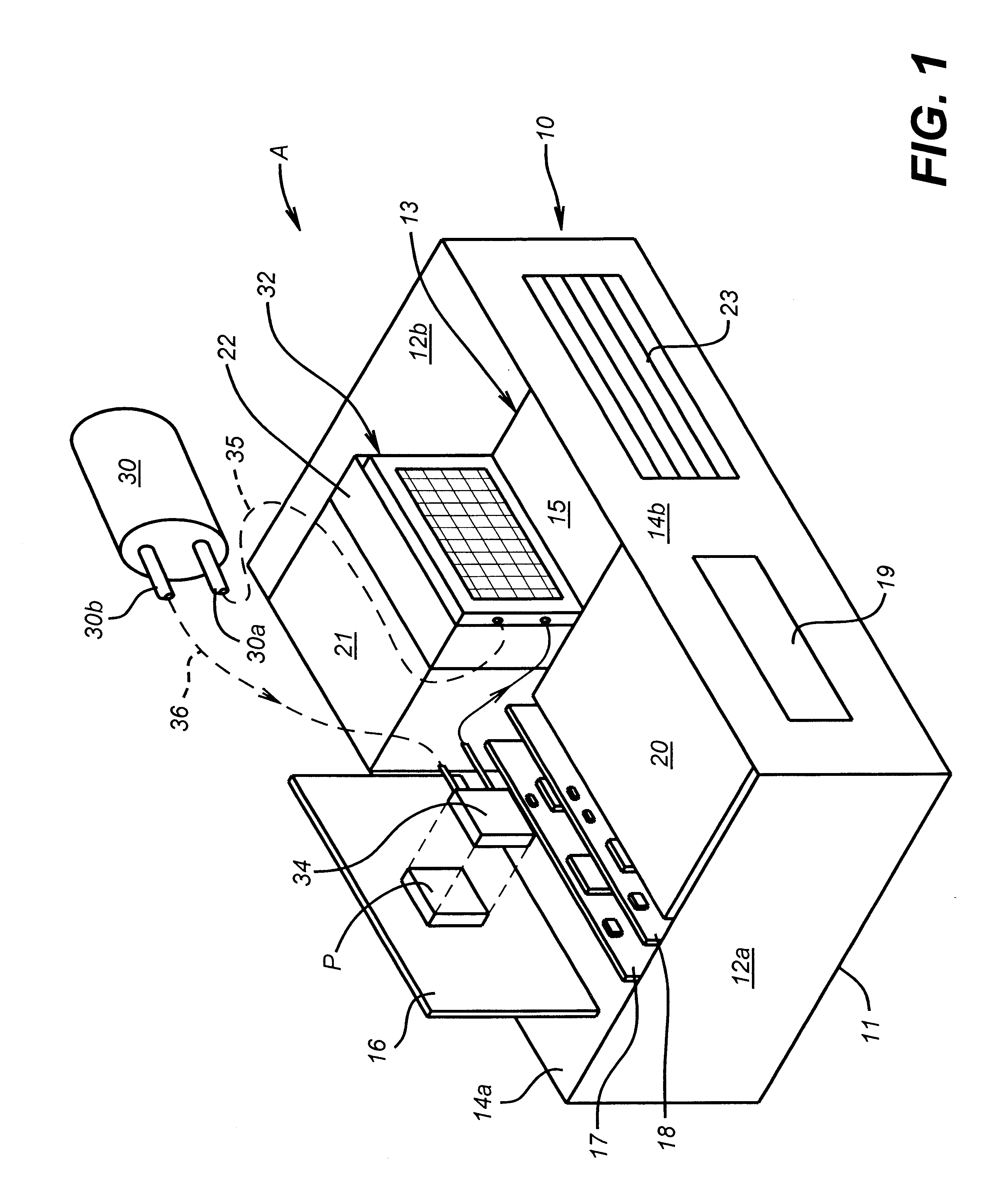
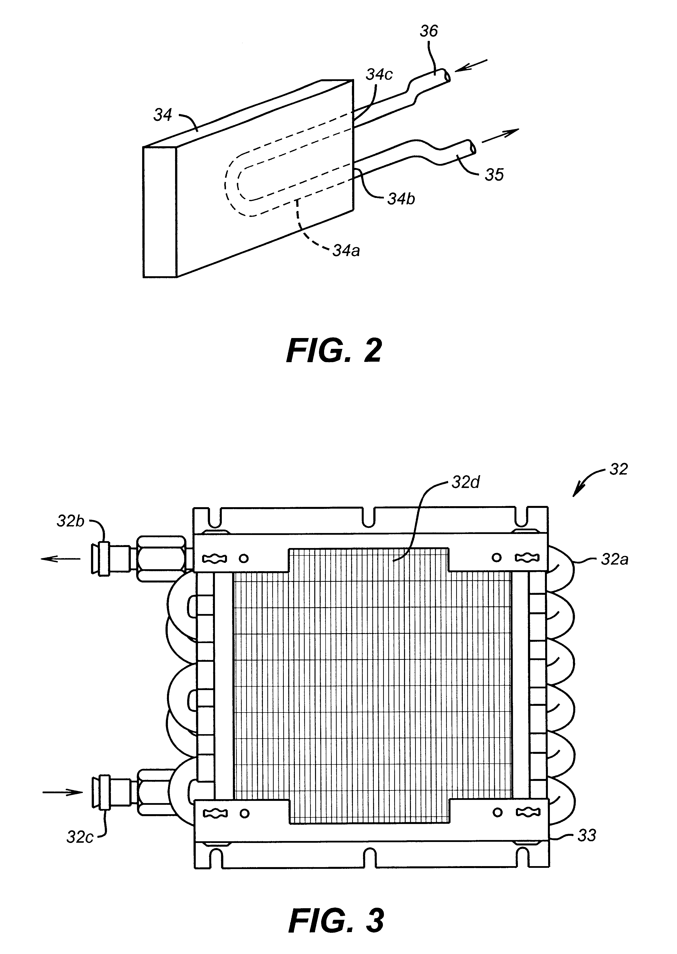
Referring to the drawings and in particular to FIGS. 1-3, apparatus generally designated as A is illustrated for continuously cooling a high heat generating component P such as the Pentium.RTM. manufactured by Intel Corporation, which generates high heat due to its power requirements. When the Pentium.RTM. chip was first developed by Intel, Intel proposed that the Pentium.RTM. chip be cooled by a combination of a heat sink and air flow, with the size of the heat sink and the amount of air flow being interrelated. Public specifications for early versions of the Pentium.RTM. chip included maximum power for a 66 MHZ Pentium.RTM. processor of a PGA package type of 16W, having a package size of 2.16".times.2.16" and a maximum case operating temperature of 70.degree. C. Intel further disclosed as specifications that the maximum device junction temperature for such a Pentium.RTM. processor was 90.degree. C.

Within a typical computer housing, it is known that ambient air should be in the ran...


PUM


Abstract

Apparatus is provided for a heat transfer assembly for direct attachment to a high heat generating chip, which assembly includes a pump, air side heat exchanger mounted adjacent to a fan and a heat transfer plate which is attached to the high heat generating component for dissipating heat from such component under operating conditions. In another embodiment, apparatus is provided for dissipating heat from a hard disk drive including a U-shaped heat exchange clip resiliently mounted on opposite surfaces of a hard disk drive. In another embodiment, apparatus for dissipating heat from a hard disk drive includes a generally rectangular plate for mounting on the top or bottom of the hard disk drive. And, in another embodiment, apparatus is provided transferring heat from a vertical array of hard disk drives, which apparatus includes one or more panels interposed between adjacent vertically disposed hard disk drives.

Description

The present invention relates to apparatus for liquid cooling by conduction of specific computer components mounted within a housing for a computer in order to reduce the operating temperature of such components.As certain components for computers, such as microprocessors or hard disk drives become more powerful and complex, while maintaining compact size, more effective thermal management becomes necessary in order to maintain desirable operating temperatures. It is well known that according to the Arrhenius equation, there is an exponential increase in failure rates with incremental increases in operating temperatures. For example, assuming a 1.0 eV activation energy, the failure rate doubles for every 10.degree. rise in operating temperature. Therefore, increases in power of computer chips such as the Pentium.RTM. requires more effective heat management techniques to prevent undesirable rises in operating temperatures.It is known to apply air-cooled fin modules directly to electr...

Claims


Application Information

Patent Timeline
Patent Type & Authority Patents(United States)
IPC IPC(8): G06F1/20H05K7/20
CPCG06F1/203G06F2200/201
Inventor DONAHOE, DANIEL N.GILL, MICHAEL T.
Owner HEWLETT PACKARD DEV CO LP
Why Eureka
Try Eureka