
Torsional vibration damper

Inactive Publication Date: 2002-01-01
ZF FRIEDRICHSHAFEN AG
View PDF7 Cites 10 Cited by
  • Summary
  • Abstract
  • Description
  • Claims
  • Application Information

AI Technical Summary

Benefits of technology

A simple, highly stable construction is achieved by joining the primary side having, respectively, two axially adjacent supporting areas with an annular carrier part. In addition, the annular carrier part may take over additional functions such, for example, as the guidance of sliding elements of the damper spring arrangements.
A particularly stable and easy-to-produce construction is achieved when at least one of the first and second supporting areas is connected with the carrier part by welding.

Problems solved by technology

Accordingly, the assembly of the torsional vibration is complex.

Method used


Image

  • Torsional vibration damper
  • Torsional vibration damper
  • Torsional vibration damper

Examples


Embodiment Construction

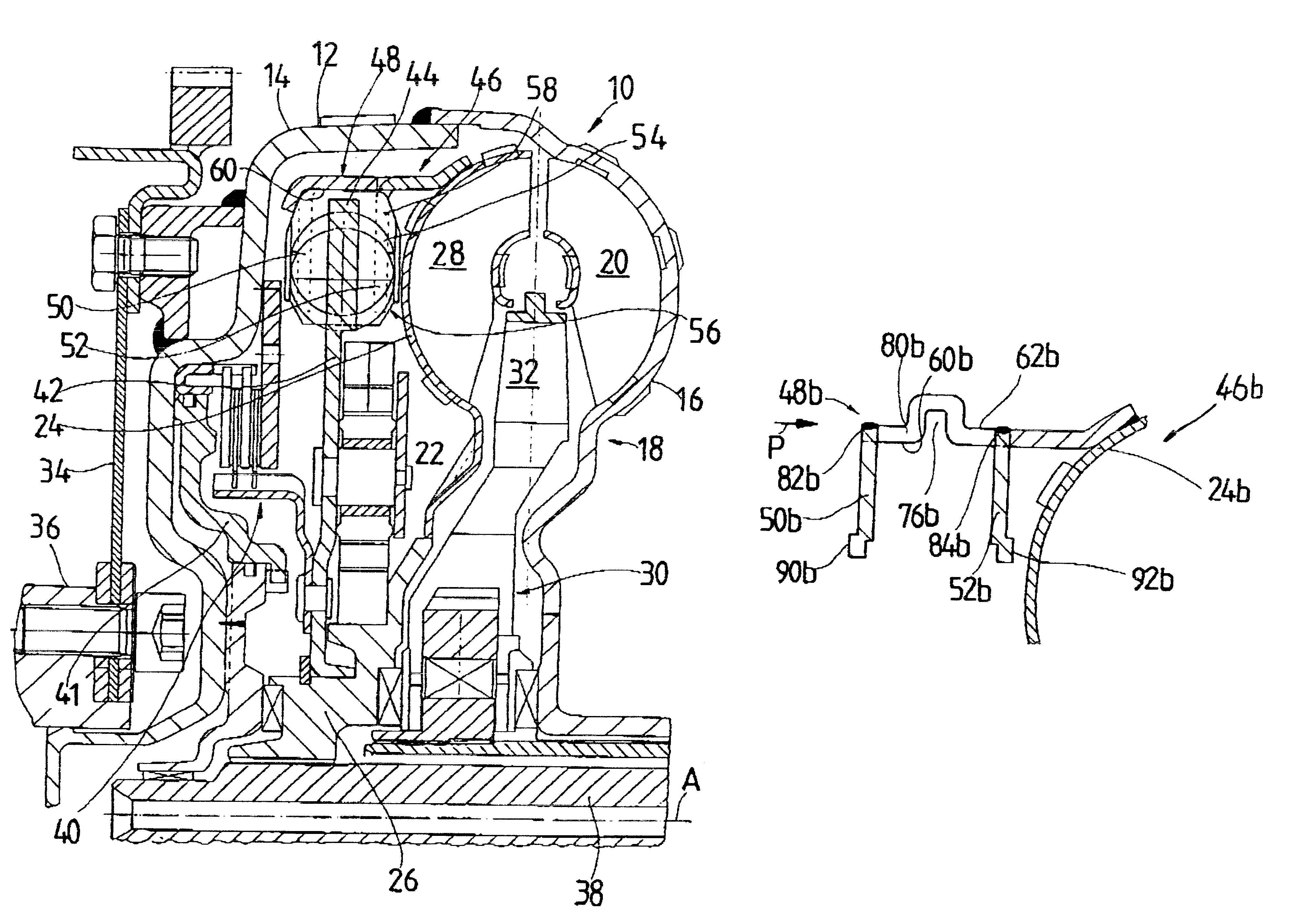
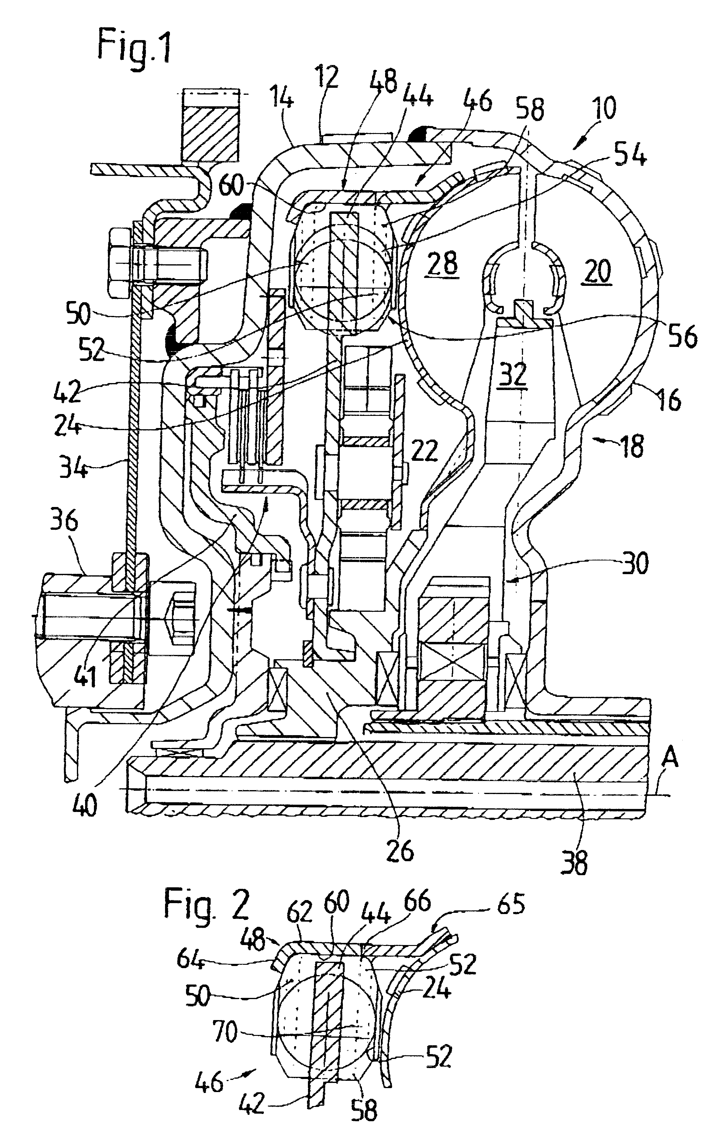
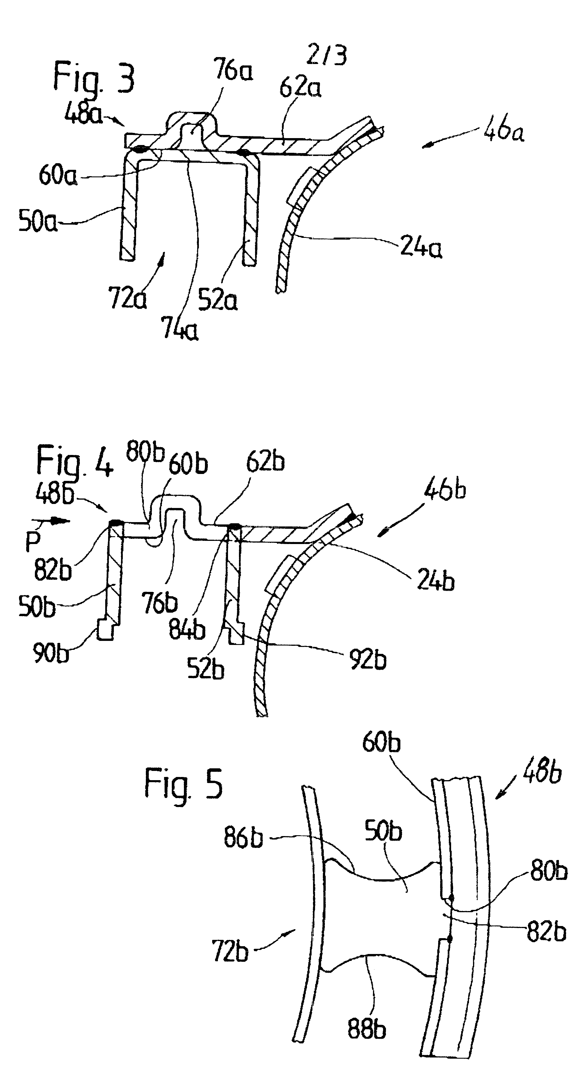
FIG. 1 shows a hydrodynamic torque converter 10 with a torsional vibration damper 46 according to an embodiment of the present invention. The construction of the torque converter is known in principle and will be described briefly in the following. The torque converter 10 has a housing 12 including a housing cover 14 and an impeller wheel shell 16 of an impeller wheel 18. The connection of the impeller wheel shell 16 to the housing cover 14 is made by welding. The impeller wheel shell 16 carries a plurality of impeller wheel blades 20 along an inner side. A turbine wheel 22 is arranged in the interior of the torque converter 10 and includes a turbine wheel shell 24 and a turbine wheel hub 26. A plurality of turbine wheel blades 28 are positioned in a successive manner in the circumferential direction in the turbine wheel shell 24. A stator wheel 30 having a plurality of stator wheel blades 32 is located between the turbine wheel 22 and the impeller wheel 18.

The converter housing 12 ...


PUM


Abstract

A torsional vibration damper, especially for transmission of torque in a hydrodynamic torque converter, includes a primary side, a secondary side, and a plurality of damper spring arrangements arranged between the primary side and the secondary side such that the primary side is rotatable relative to the secondary side against an urgency of the damper spring arrangement. Each damper spring arrangement has at least one spring and is supported in each circumferential end area at a supporting area of the secondary side and at a first and a second supporting area of the primary side which are arranged on both axial sides of the associated supporting area of the secondary side. The primary side has a substantially annular carrier part and at least one of the first and second supporting areas of the primary side are constructed as separate parts that are connected for rotation with the primary side.

Description

1. Field of the InventionThe present invention is directed to a torsional vibration damper, comprising a primary side, a secondary side and a plurality of damper spring arrangements, wherein every damper spring arrangement comprises at least one spring and can be supported in each circumferential end area at a supporting area of the secondary side and at a first and a second supporting area of the primary side which are arranged on both sides of the associated supporting area of the secondary side. More specifically, the present invention is directed to a torsional vibration for transmission of torque in a hydrodynamic torque converter.2. Description of the Related ArtA prior art hydrodynamic torque converter is disclosed by DE 197 24 973 C1 having a torsional vibration damper arranged in a torque transmission path between a lockup clutch and a turbine wheel hub. This torsional vibration damper has a hub disk which is connected to a hub and which forms a plurality of supporting area...

Claims


Application Information

Patent Timeline
IPC IPC(8): F16F15/123F16F15/12F16F15/121
CPCF16F15/1203F16F15/1232F16H2045/0284F16H45/02
Inventor WACK, ERWINKUNDERMANN, WOLFGANGSUDAU, JORGSASSE, CHRISTOPH
Owner ZF FRIEDRICHSHAFEN AG
Learn More