Projection screen for image reproduction devices which are positioned next to and/or above one another

a technology of projection screen and image, which is applied in the direction of instruments, television systems, optics, etc., can solve the problems of affecting the connection between, affecting the distance between the basic units, and fragile edges of the basic units of this natur

Inactive Publication Date: 2002-01-01
BARCO NV
View PDF8 Cites 50 Cited by
  • Summary
  • Abstract
  • Description
  • Claims
  • Application Information

AI Technical Summary

Benefits of technology

The object of the present invention is t

Problems solved by technology

Changing climatological conditions, such as temperature and relative atmospheric humidity, may alter the distance between the basic units and have an adverse effect on the connection between them.
However, the edges of a basic unit of this nature are fragile during transportation and the other drawbacks which are inherent to the assembly of basic units continue to exist.
The vertical seams between screen panels of horizontally neighboring basic units are however not sufficiently minimised.
Attaching basic units of this nature to one another not only has the abovementioned drawbacks which are inherent to the use of relatively large single screens or adhesively-bonded larger screens, but also drawbacks which are inherent to modular multi-screen displays assembled from identical basic units, such as the need for a flat and stable base and the fact that the connection between the basic units is dependent on temperature and humidity.
The abovementioned multi-screen displays which are known from the prior art are difficult to transport owing to their large dimensions and fragility and for installation often require lifting mechanisms, a large space around them and a number of qualified fitters.
During installation, it is difficult or impossible to compensate for production tolerances in the dimensions of the components to be assembled and it is impossible to guarantee an optimum connecti

Method used


Image

  • Projection screen for image reproduction devices which are positioned next to and/or above one another
  • Projection screen for image reproduction devices which are positioned next to and/or above one another
  • Projection screen for image reproduction devices which are positioned next to and/or above one another

Examples


first preferred embodiment

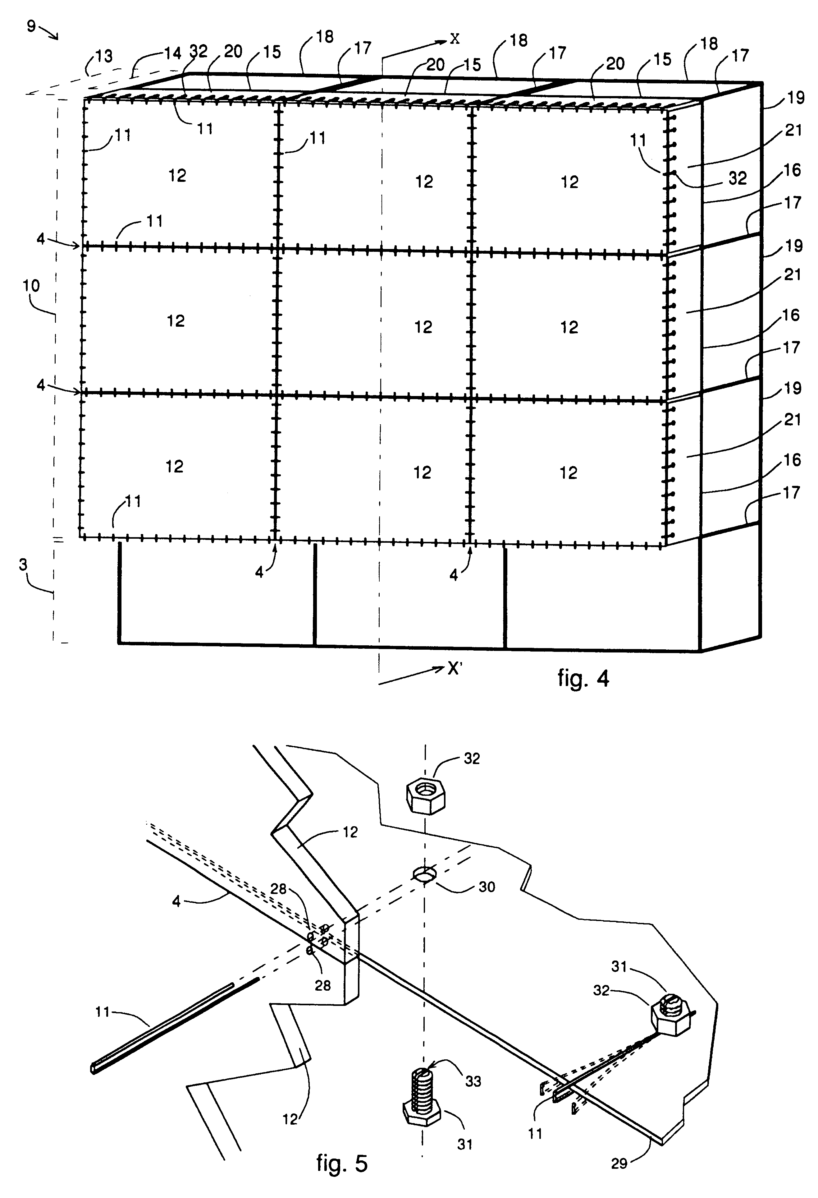
A single extruded section is used for the horizontal and vertical profile sections 15, 16; the horizontal profile sections 15 are longer than the vertical profile sections 16.

FIG. 12 shows the intersection between two horizontal profile sections 15, two vertical profile sections 16 and a lateral profile section 17. The horizontal and vertical profile sections 15, 16 present two longitudinal slots on the front side, namely a central slot 25 for the attachment of a vertical attachment plate 21 and a lateral slot 26 for the attachment of a horizontal attachment plate 20. A T-slot is provided on the rear side of the horizontal and vertical profile sections 15, 16 for fixing these profile sections 15, 16 to a lateral profile section 17 via attachment elements 27 and using coach bolts and nuts as described in BE-9601054. This lateral profile section 17 differs from the horizontal and vertical profile sections 15, 16 in that it is substantially square in cross-section, and that it has at l...

second preferred embodiment

FIG. 17 shows the intersection between two horizontal profile sections 15, two vertical profile sections 16 and a lateral profile section 17. A single extruded section is used for the horizontal, vertical and lateral profile sections 15, 16 and 17. In this second preferred embodiment, the horizontal profile sections 15 are longer than the vertical profile sections 16 to obtain an aspect ratio of 4 / 3. The profile sections 15, 16, 17 have four equal sides in which a T-slot is provided for fixing profile sections to one another or for the fixation of other items to the profile sections. At the location where horizontal and vertical profile sections 15, 16 come together at an intersection as shown in FIG. 17 or at an edge of the projection screen 9, the horizontal and vertical profile sections 15, 16 are all fixed to the same lateral profile section 17 via attachment elements 27 and using coach bolts and nuts as described in BE-9601054.

second embodiment

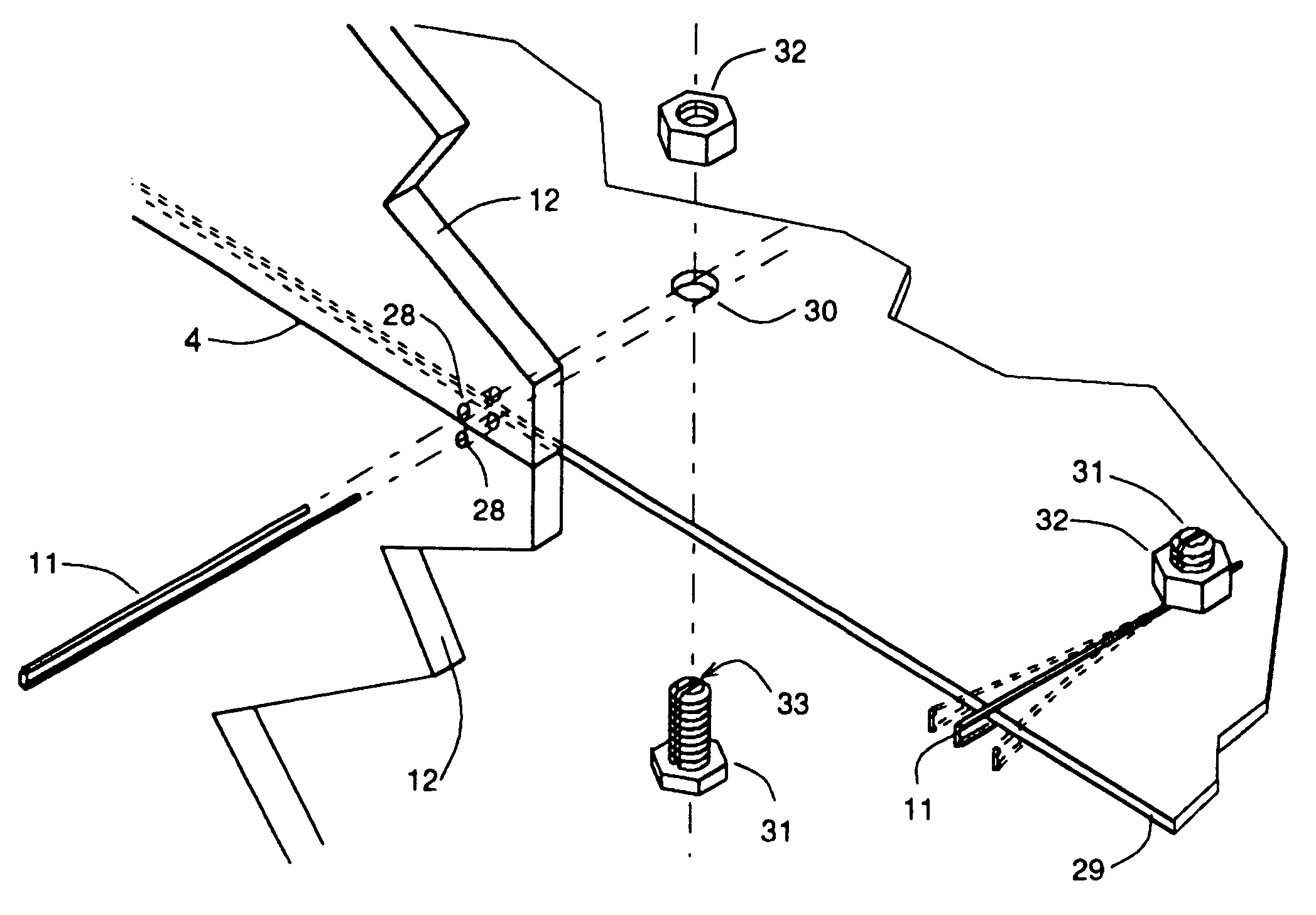
The second embodiment differs from the first embodiment in the attachment plates 20, 21, the profile sections 15, 16, 17 and the attachment between said attachment plates 20, 21 and said profile sections 15, 16, 17. The screen panels 12 and their attachment to one another and to attachment plates 20, 21 by means of joining wires 11, and the joining wires 11 themselves are identical for both preferred embodiments, and therefore is referred here to the description of these common and identical parts of both embodiments in the description of the first embodiment.

FIG. 18a shows the two parts of a horizontal attachment plate 20, being a top metal plate 68 and a bottom metal plate 69.

The bottom metal plate 69 has two perpendicular planes, being a plane 70 and a raised edge 71. In the raised edge 71 are holes 72 for the fixation of the bottom metal plate 69 to the supporting structure 13 e.g. by means of bolts 66 and nuts 67 as shown in FIG. 17. In the plane 70 of the bottom metal plate 69...


PUM


Abstract

A multi-screen display for rear projection applications includes a supporting structure and a screen comprising a plurality of screen panels which are positioned and attached to one another and to attachment plates by joining wires. The seams between the screen panels are minimal, specifically less than half of a millmetre wide, even in the event of relatively inaccurate installation of the projection screen, in spite of manufacturing tolerances and under changing climatological conditions, such as temperature and relative atmospheric humidity, owing to the fact that the attachment plates to which the screen panels are fixed using the joining wires are deformable and/or movably joined to the supporting structure.

Description

The present invention relates to a projection screen for image reproduction devices which comprise projectors and screens, an image being projected onto the rear side of a screen with the aid of a projector. The field of application is that of multi-screen displays.In the case of a multi-screen display of this nature, the viewer is situated in front of the screens, which are positioned next to and / or above one another, optionally at an angle, so that they form an image surface onto which an image, optionally composed of a plurality of subimages, can be projected. A subimage may cover one or more screens of the image surface and may occur at any desired location on the image surface. These subimages may be projected dependently or independently. The images may be moving or still.In the case of multi-screen displays, there are the same number of (at least two) projectors as screens for projecting images onto the screens. As a result of their layout, the screens form a surface in the s...

Claims


Application Information

Patent Timeline
IPC IPC(8): G03B21/10H04N5/74
CPCH04N9/3147G03B21/10
Inventor VAN DE VOORDE, TOMMY
Owner BARCO NV
Why Eureka
Try Eureka