Rotary damper

a technology of rotary dampers and dampers, which is applied in the direction of shock absorbers, wing accessories, manufacturing tools, etc., can solve the problems of high machining precision, large number of viscous fluid m, and inability to provide sufficient and satisfactory, so as to achieve the effect of reliably providing the damper

Inactive Publication Date: 2002-01-08
SUGATSUNE IND CO LTD
View PDF18 Cites 73 Cited by
  • Summary
  • Abstract
  • Description
  • Claims
  • Application Information

AI Technical Summary

Benefits of technology

With such an arrangement, torque is generated in the damper due to the considerably large frictional force that arises between the inner peripheral surface of the casing and the eccentric resilient section when the movable shaft is driven to rotate toward the free end of the eccentric resilient section, whereas the frictional force can be reduced greatly without providing the viscous fluid with a specific flow path unlike the prior art that utilizes the viscous shearing resistance of the viscous fluid when the movable shaft is subjected to a rotary force trying to rotate it in the opposite sense. Thus, a large torque can be obtained in the damper principally comprising only two components without requiring an enhanced level of machining precision.
Still preferably, the torque of the damper can reliably be provided to a large extent by the eccentric resilient section without using any additional member simply by arranging a projection in the casing.

Problems solved by technology

Thus, the rotary damper A as described above is accompanied by a number of drawbacks including that it cannot provide a sufficient and satisfactory damping effect when the viscous shearing resistance is used as a sole source of damping power, that it requires a high level of machining precision because the torque of the damper changes from the expected value if the size of the gap varies from the designed value, that the components including the casing e, the movable shaft h, the O-rings k1, k2 and the viscous fluid m are large in number and costly and that, while the torque of the damper effectively operates when the keyboard lid b is closed, a substantially same viscous shearing resistance appears also when the keyboard lid b is opened.

Method used


Image

  • Rotary damper
  • Rotary damper
  • Rotary damper

Examples


Embodiment Construction

Now, the present invention will be described by referring to the accompanying drawings that illustrate preferred embodiments of the invention.

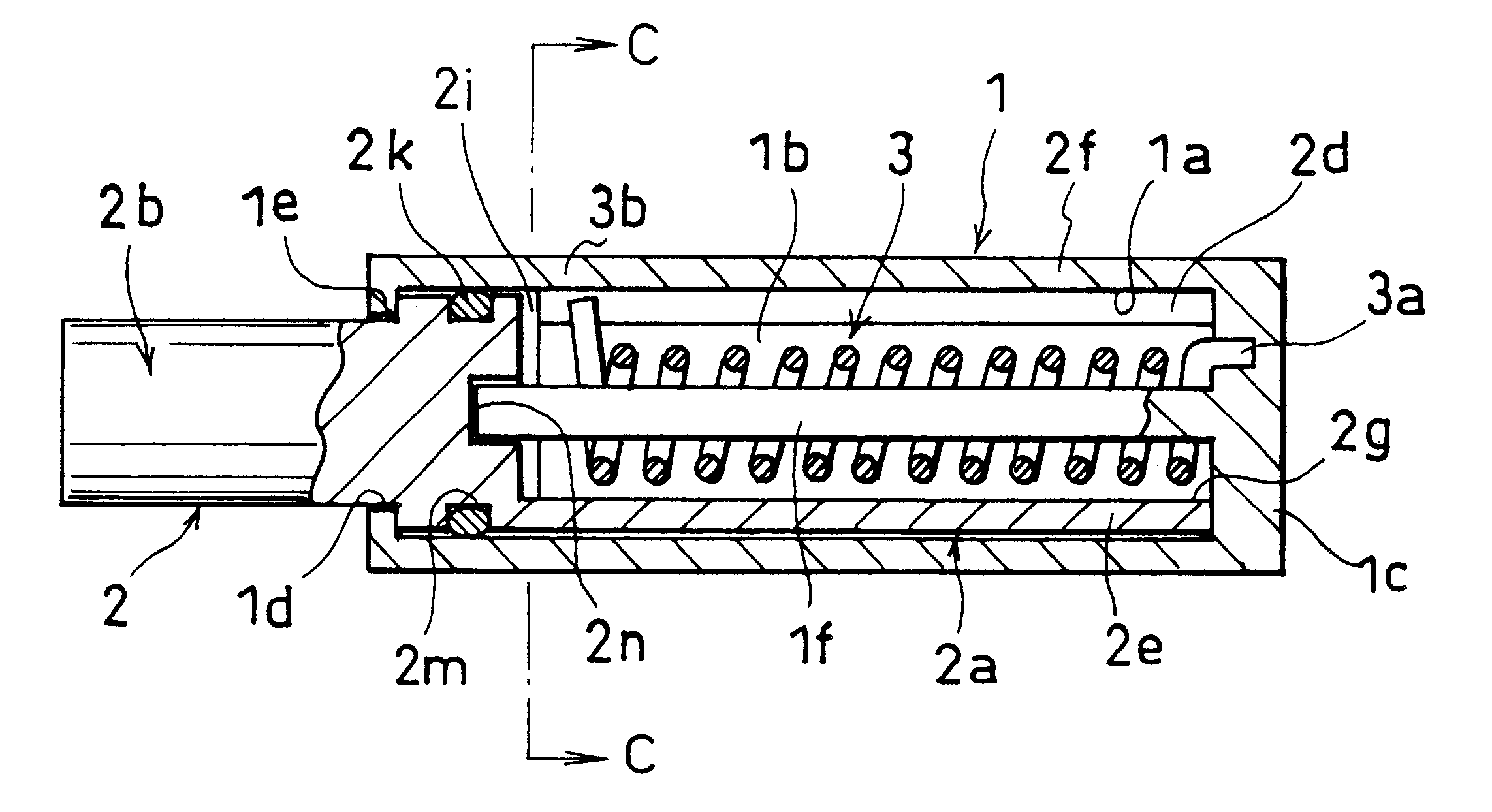
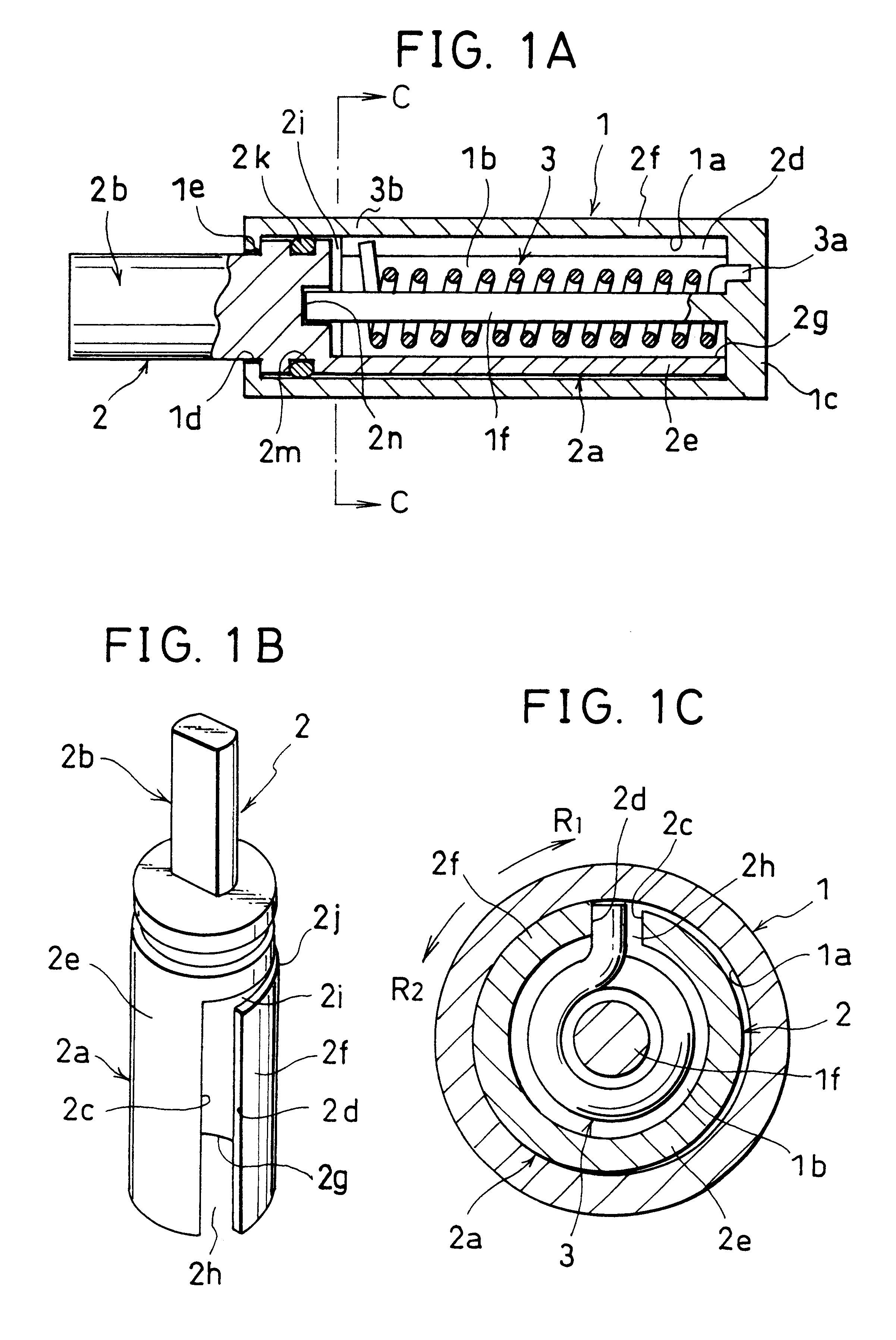
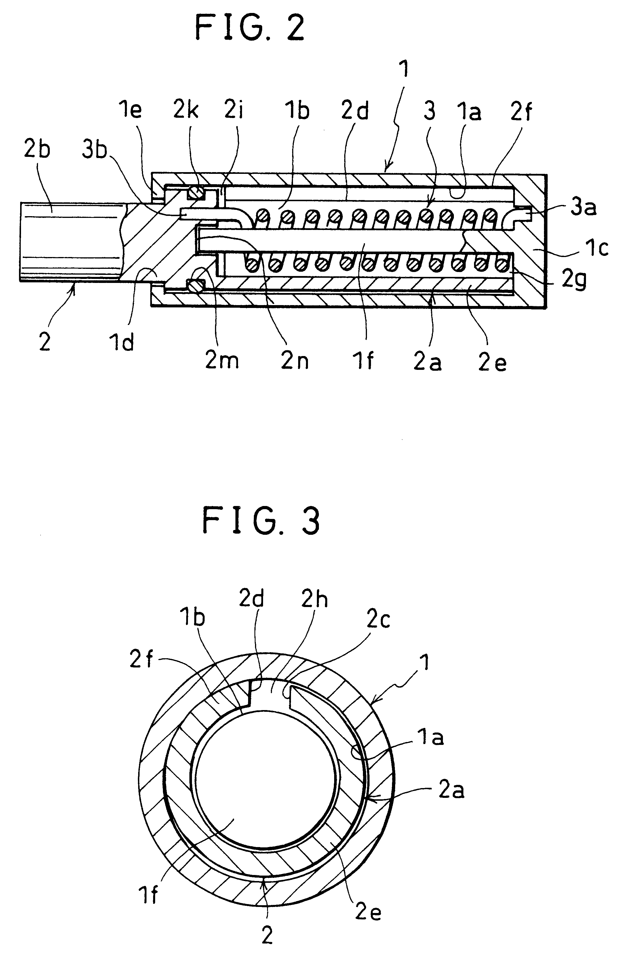
FIGS. 1A through 1C schematically illustrate an embodiment of a rotary damper according to the invention comprising a casing 1 and a movable shaft 2. The casing 1 is rigidly secured to a predetermined position and the movable shaft 2 is linked to a door, a toilet lid or the like. However, it may be so arranged that inversely the movable shaft 2 is rigidly secured to a predetermined position and the casing 1 is made to be movable with a door or the like.

Said casing has in it a cavity 1b defined by the inner peripheral surface 1a of the casing and dosed at an end thereof by a closure section 1c but open at the other end to provide an opening 1d there.

On the other hand, the movable shaft 2 has a cylindrical shaft section 2a loosely and rotatably contained in the cavity 1b of the casing 1 but unreleasably held in the cavity 1b by an anti-release e...


PUM


Abstract

A rotary damper is adapted to exert braking force to an upswung door, a toilet lid or the like when the door is closed and dampen the impact produced by the closing door by a damping force far greater than the one obtained by a conventional rotary damper using viscous shearing resistance. The rotary damper can also make the door open by a force far smaller than a conventional rotary damper. A movable shaft is rotatably housed in a casing and has a cylindrical shaft section including an arcuate non-resilient section extending from a peripheral edge thereof to an axial base line close to the other free peripheral edge thereof and an eccentric resilient section extending from the axial base line to the other free peripheral edge thereof with its eccentricity increasing as a function of the distance from the base line relative to the radius of curvature of the inner peripheral surface so as resiliently abut the inner peripheral surface. The frictional force between the eccentric rest section and the inner peripheral surface increases when the movable shaft is driven to rotate to close the door to which it is fitted but falls remarkably when the movable shaft is driven to rotate in the opposite sense to open the door.

Description

1. Field of the InventionThis invention relates to an improvement to a rotary damper to make it operate as a shock absorber and act on a turning body such as a door or a toilet lid when the latter is falling down to the closed position.2. Description of Related Background ArtJapanese Utility Model Laid-Open No. 62-81739 discloses a rotary damper of the type under consideration as shown in FIGS. 7A and 7B of the accompanying drawings.Referring to FIGS. 7A and 7B, which illustrate an embodiment of a rotary damper according to the above document and adapted to be used for the keyboard lid of a piano. The rotary damper A is linked to the keyboard lid b by way of a join d so that the keyboard lid b may be closed smoothly at an appropriate moving speed without emitting a large bumping sound and / or vibrating violently when it gets to the final closed position.As seen from FIG. 7B, the rotary damper A comprises a casing e, a movable shaft h loosely fitted into the inner cavity g of the casi...

Claims


Application Information

Patent Timeline
Patent Type & Authority Patents(United States)
IPC IPC(8): E05F1/00E05F3/14E05F3/00E05F1/08E05C17/00E05C17/64F16F9/12F16F9/10F16F7/00F16F7/04F16F
CPCF16F7/06F16F9/12Y10T16/2771Y10T16/304Y10T16/53888Y10T16/54038
Inventor BANDO, RYOSUKE
Owner SUGATSUNE IND CO LTD
Why Eureka
Try Eureka