Fluorescent X-ray analyzer

a fluorescent x-ray and analyzer technology, applied in the direction of material analysis using wave/particle radiation, instruments, diaphragm/collimeter handling, etc., can solve the problem that the s/n ratio cannot be improved sufficiently

Inactive Publication Date: 2002-01-08
RIGAKU CORP
View PDF2 Cites 28 Cited by
  • Summary
  • Abstract
  • Description
  • Claims
  • Application Information

AI Technical Summary

Problems solved by technology

However, the use of the collimator 10B has been found having such a problem that as shown in FIG. 22, when the fluorescent X-rays 5 emanating from the sample piece 1 are partially cut off by, for example, the tube 15a, a portion 5a of the fluorescent X-rays 5 emanating from the sample piece 1 tend to impinge

Method used


Image

  • Fluorescent X-ray analyzer
  • Fluorescent X-ray analyzer
  • Fluorescent X-ray analyzer

Examples


second embodiment

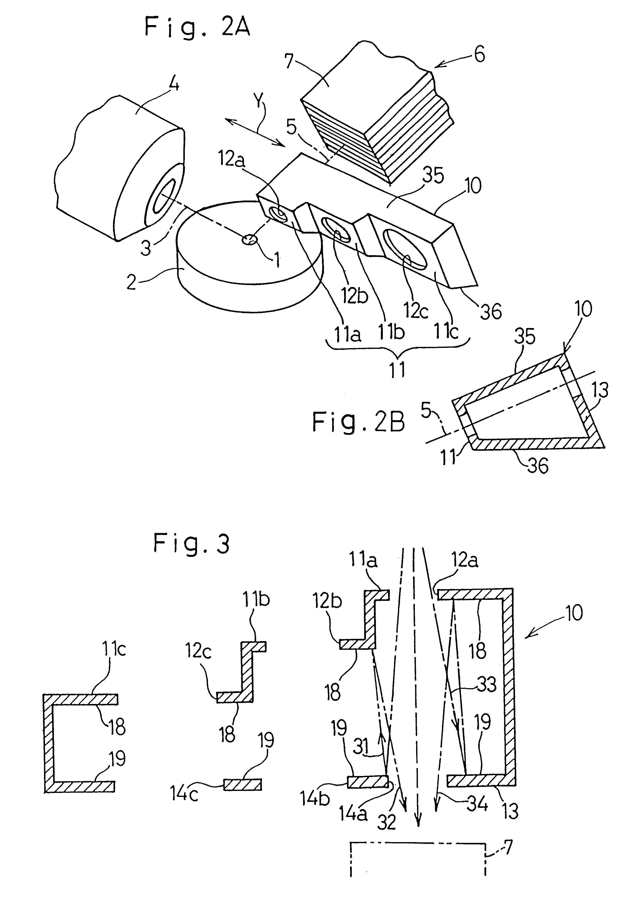
Accordingly, where the diameter of the target area to be measured is large, one of the apertures 42a to 42c in the oblong plate member of the second collimator 40 is selected. In such case, although there is a relatively large distance between any one of the apertures 42a, 42b and 42c in the second collimator 40 and the target area to be measured, detection of the disturbing rays can be effectively and sufficiently avoided since the diameter of the target area to be measured is large. In this way, the provision of the second collimator 40 between the first collimator 10 and the detecting means 6 is effective to reduce the length of the first collimator 10 in the direction Y as compared with the length which the first collimator 10 would assume if six apertures were to be formed in a row in the first collimator 10. Reduction in length of the first collimator 10 is in turn effective to avoid any possible increase of the distance the first collimator 10 must move in the direction Y and...

first embodiment

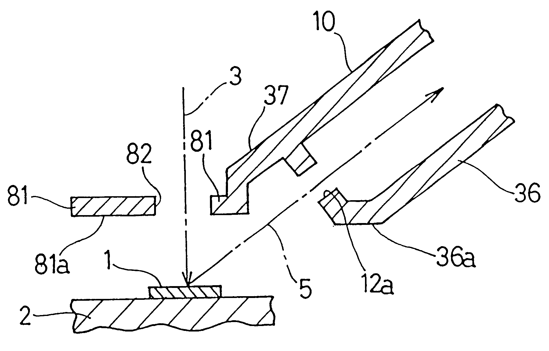
Assuming that the diameter of the target area to be measured is one of D1, D2 and D3, one of the apertures 12a to 12c in the first collimator 10 which corresponds to the diameter of the target area to be measured is brought into alignment with the path of travel of the fluorescent X-rays 5 between the sample piece 1 and the detecting means 6 as is the case with the present invention. At this time, the second collimator 40 is retained in the retracted position out of the path of travel of the fluorescent X-rays 5.

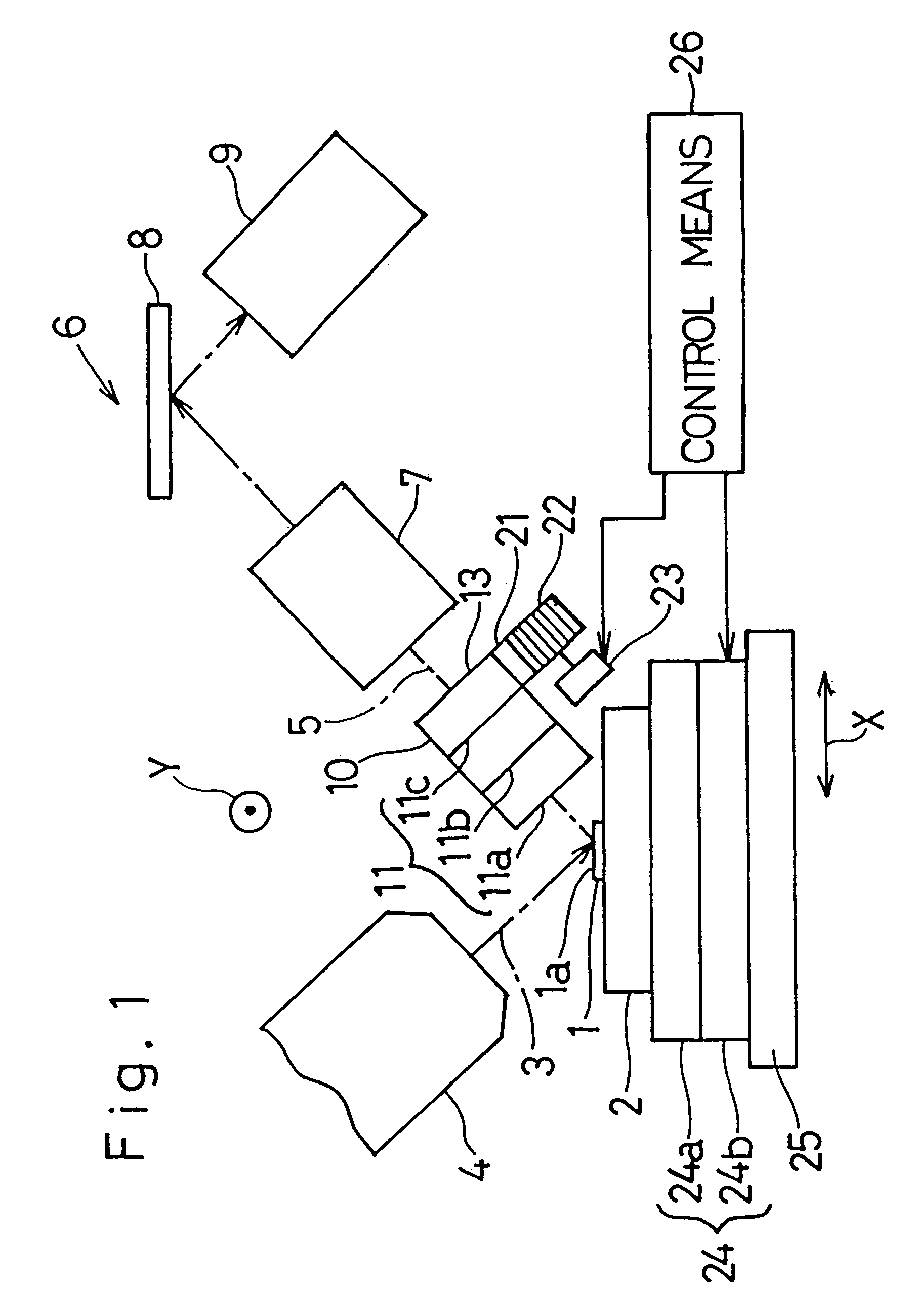
In the event that the diameter of the target area of the sample piece 1 is large, and when instruction indicating that the diameter of the target area to be measured is one of D3, D4 and D5 is inputted to the control means 26, the control means 26 controls the X-Y stage 24 so that the sample table 2 can be moved to a position at which the radiation intensity of the primary X-rays 3 towards the target area of the sample piece 1 to be measured is maximum. Simultaneously therew...

third embodiment

The fluorescent X-ray analyzer according to the present invention operates in the following manner.

The manner in which the fluorescent X-rays are partially cut off by selecting one of the apertures 12a to 12c in the first collimator 10 or one of the apertures 42a and 42b in the second collimator 40 is substantially similar to that employed in the practice of any one of the first and second embodiments of the present invention.

Where the target area of the sample piece 1 to be measured is small, the aperture 12d in the second hollow projection 62 is selected, in which case the second collimator 40 is moved in the direction Y to assume a potion rearwards of the aperture 12d and the fluorescent X-rays 5 passing through the aperture 12d are detected by the SSD 43. The SSD 43 is of an energy dispersive type and is capable of examining roughly the X-ray spectra from the sample piece without monochromatizing. Even when any one of the apertures 12a to 12c in the first hollow projection 61,th...


PUM


Abstract

A fluorescent X-ray analyzer includes a detector (6) for detecting fluorescent X-rays (5) emitted from a sample piece (1) to be analyzed, and a first collimator (10) disposed between the sample piece (1) and the detector (6) supported for movement between inserted and retracted positions with respect to a path of travel of the fluorescent X-rays (5) towards the detector (6). The first collimator (10) comprises a wall (11) adjacent the sample piece (1) that is stepped to provide stepped wall segments (11a, 11b, 11c) having respective apertures (12a, 12b, 12c) of varying diameters defined therein. The smaller the aperture, the closer it is to the sample piece (1) when one of the apertures (12a, 12b, 12c) is selected according to a size of a target area of the sample piece (1) to be measured and is then brought in register with the path of travel of the fluorescent X-rays (5) towards the detector (6).

Description

1. Field of the InventionThe present invention generally relates to a fluorescent X-ray analyzer and, more particularly, to the fluorescent X-ray analyzer of a type provided with a collimator for restricting the field of view so that fluorescent X-rays and / or scattering X-rays generated from sources other than a sample piece being analyzed will not reach a detecting means.2. Description of the Prior ArtGenerally in a fluorescent X-ray analyzer utilizing parallel beams, as shown in FIG. 19, a sample piece 1 fixedly supported on a sample table is generally radiated with primary X-rays 3 generated from an X-ray tube 4 to excite the sample piece 1. The sample piece 1 so excited generates fluorescent X-rays 5 which are subsequently guided through a collimator 10A to a solar slit 7 to extract the fluorescent X-rays 5 in the form of parallel beams. The fluorescent X-rays 5 emerging from the solar slit 7 are subsequently monochromatized by a monochromator 8 according to spectrum of differen...

Claims


Application Information

Patent Timeline
IPC IPC(8): G01N23/223G01N23/22G21K1/02G21K1/06
CPCG01N23/223G21K1/02G01N2223/076
Inventor KAWAHARA, NAOKIAOYAGI, KOUICHI
Owner RIGAKU CORP
Why Eureka
Try Eureka