High efficiency medical nebulizer

a nebulizer and high efficiency technology, applied in the direction of machines/engines, combustible gas purification/modification, separation processes, etc., can solve the problems of large variance in medication delivery efficiency, low efficiency of nebulizers currently on the market, and inability to precisely control the aerosol production process of pneumatic nebulizers

Inactive Publication Date: 2002-01-15
MERCURY ENTERPRISES
View PDF17 Cites 160 Cited by
  • Summary
  • Abstract
  • Description
  • Claims
  • Application Information

AI Technical Summary

Problems solved by technology

Large variances in fact exist in medication delivery efficiency between different nebulizers, with nebulizers currently on the market falling at the low end of the possible efficiency spectrum.
Aerosol production within a pneumatic nebulizer is not a precisely controlled process.
Additionally the solution which is evaporated off the inside surfaces of the nebulizer, results in solute adhering to the nebulizer surface where it is lost to the patient permanently.

Method used


Image

  • High efficiency medical nebulizer
  • High efficiency medical nebulizer
  • High efficiency medical nebulizer

Examples


Embodiment Construction

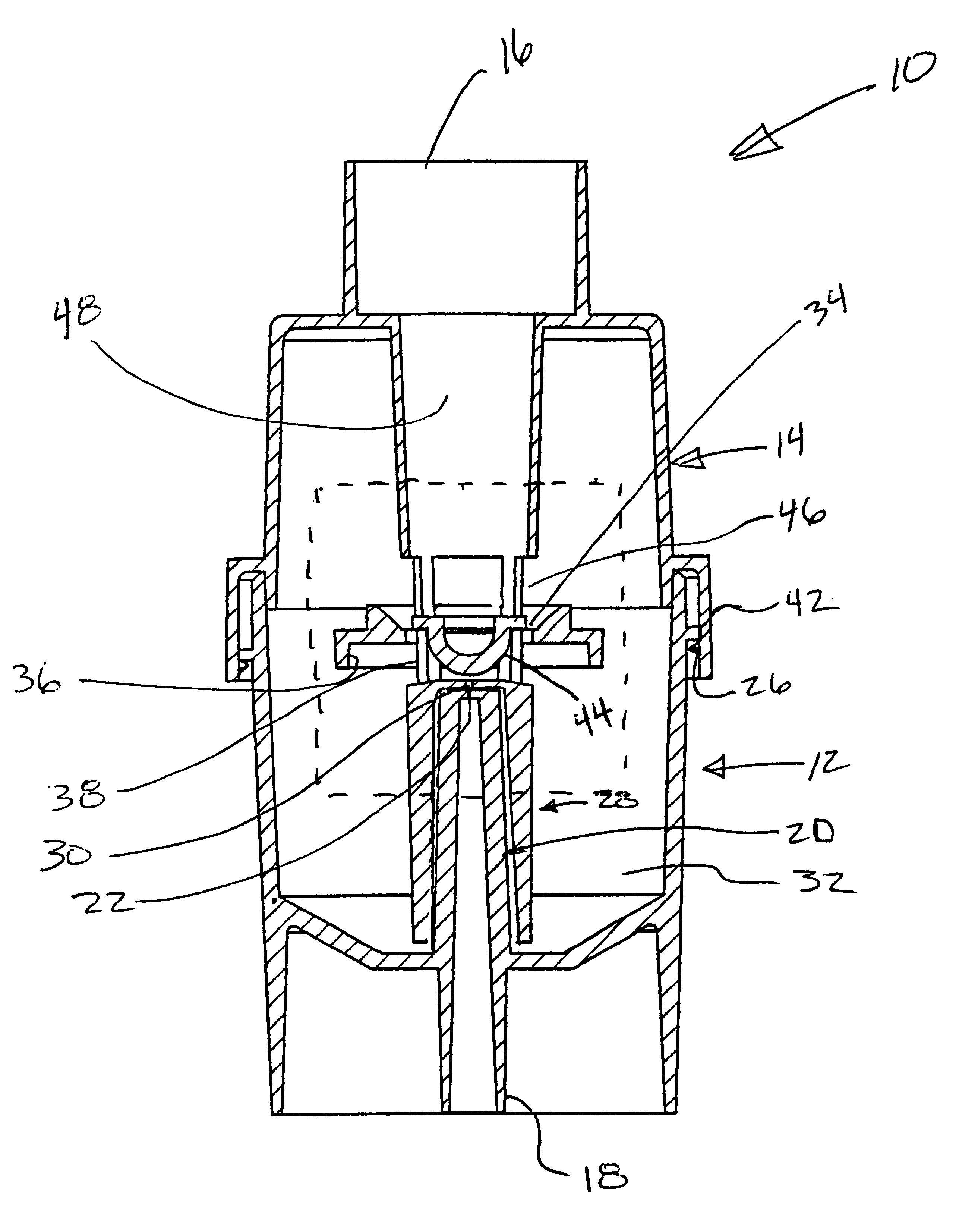
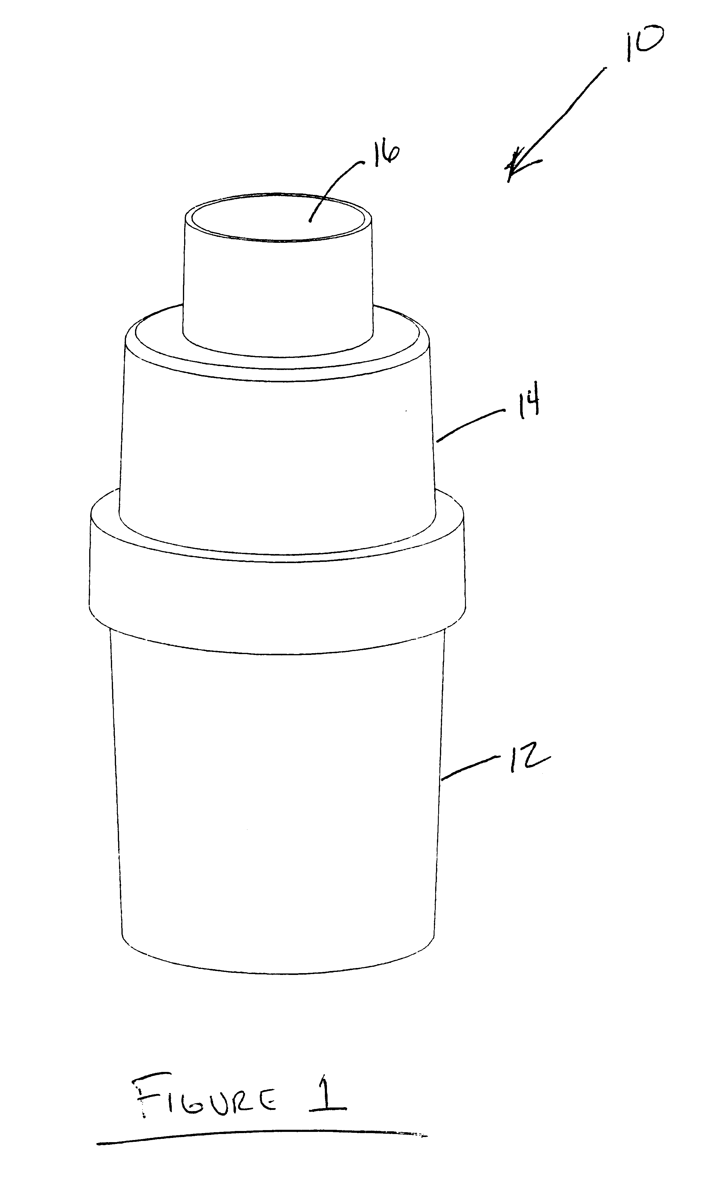
Referring more specifically to the drawings, for illustrative purposes the high efficiency nebulizer of the present invention is embodied in the apparatus generally shown in FIG. 1. It will be appreciated that the apparatus may vary as to configuration and as to details of the parts without departing from the basic concepts as disclosed herein.

Referring to FIG. 1 the nebulizer 10 of the present invention includes a solute jar 12 connected to an inhaler cap 14 that includes an aerosol outlet 16. FIG. 2 depicts the underside of the nebulizer 10 from FIG. 1, with a compressed gas inlet 18. FIG. 3 is side view of the nebulizer. FIG. 4 shows a top view of the nebulizer wherein the barrel of the aerosol outlet 16 is clearly seen. A cross-section of the disassembled structure is shown in FIG. 5 according to the section lines of FIG. 4. The solute jar 12 consists of the compressed gas inlet 18 whose tubular gas passage continues through a gas inlet column 20 that terminates in a primary ori...


PUM

PropertyMeasurementUnit
aerodynamic equivalent diameteraaaaaaaaaa
mass median diametersaaaaaaaaaa

Abstract

A pneumatic nebulizer that produces a high volume of aerosols for inhalent delivery of medications and other constituencies. High pressure gas formed into a gas jet is passed through a thin choked region of fluid that is entrailed and impinged upon an aerosol amplifier which creates a spray whose aerosol components are directed up through vents to an aerosol outlet for delivery. Larger-sized liquid particles are caused to pool up in a region surrounding the aerosol amplifer and then drip down back into the liquid medication reservoir.

Description

1. Field of the InventionThis invention pertains generally to aerosol generating devices, and more particularly to a high efficiency pneumatic nebulizer, which may be used to deliver medicinal aerosols.2. Description of the Background ArtNebulizers of various types have been widely used for inhalation delivery of aerosols containing medication or other constituents to the conductive airways of the lung and the gas exchange regions of the deep lung. Aerosols are relatively stable suspensions of finely divided droplets or solid particles in a gaseous medium, usually in air or oxygen. When inhaled, aerosol particles may be deposited by contact upon the various surfaces of the respiratory tract leading to potential injury, desirable therapeutic action, or planned diagnostic behavior depending on the particular properties of the particles. Inhalable aerosol particles are those with an aerodynamic equivalent diameter between 1 and 5 micrometers.Due largely to the high permeability of the ...

Claims


Application Information

Patent Timeline
Patent Type & Authority Patents(United States)
IPC IPC(8): A61M11/06A61M11/00
CPCA61M11/002A61M11/06
Inventor PIPER, SAMUEL DAVID
Owner MERCURY ENTERPRISES
Why Eureka
Try Eureka