Light guide plate, surface light source device of side light type and liquid crystal display

a surface light source and liquid crystal display technology, applied in the direction of identification means, lighting and heating apparatus, instruments, etc., can solve the problems of reducing the quality of illumination output, avoiding the so-called "reflective appearance of edges" insufficiently, and prior techniques are subject to problems. , to avoid the effect of reducing the quality of illumination

Inactive Publication Date: 2002-01-15
ENPLAS CORP
View PDF4 Cites 32 Cited by
  • Summary
  • Abstract
  • Description
  • Claims
  • Application Information

AI Technical Summary

Benefits of technology

An object of the present invention is to provide a light guide plate which is improved so that the above problems are overcome. Another object of the present invention is to provide a surface light source device of side light type free from uneven brigh

Problems solved by technology

However, such prior techniques are subject to a problem.
That is, so-called "reflective appearance of edges" are insufficiently avoided.
Needless to say, such a phenomenon is undesirable and leads to a remarkable reduction in illumination output quality.
If applied to lighting of a liquid crystal display panel, displaying quality will be greatly deteriorated.
Nevertheless the above techniques (1), (2) are able to reduce uneven brightness (bright lines) caused by such reflective appea

Method used


Image

  • Light guide plate, surface light source device of side light type and liquid crystal display
  • Light guide plate, surface light source device of side light type and liquid crystal display
  • Light guide plate, surface light source device of side light type and liquid crystal display

Examples


first embodiment

(1)First Embodiment

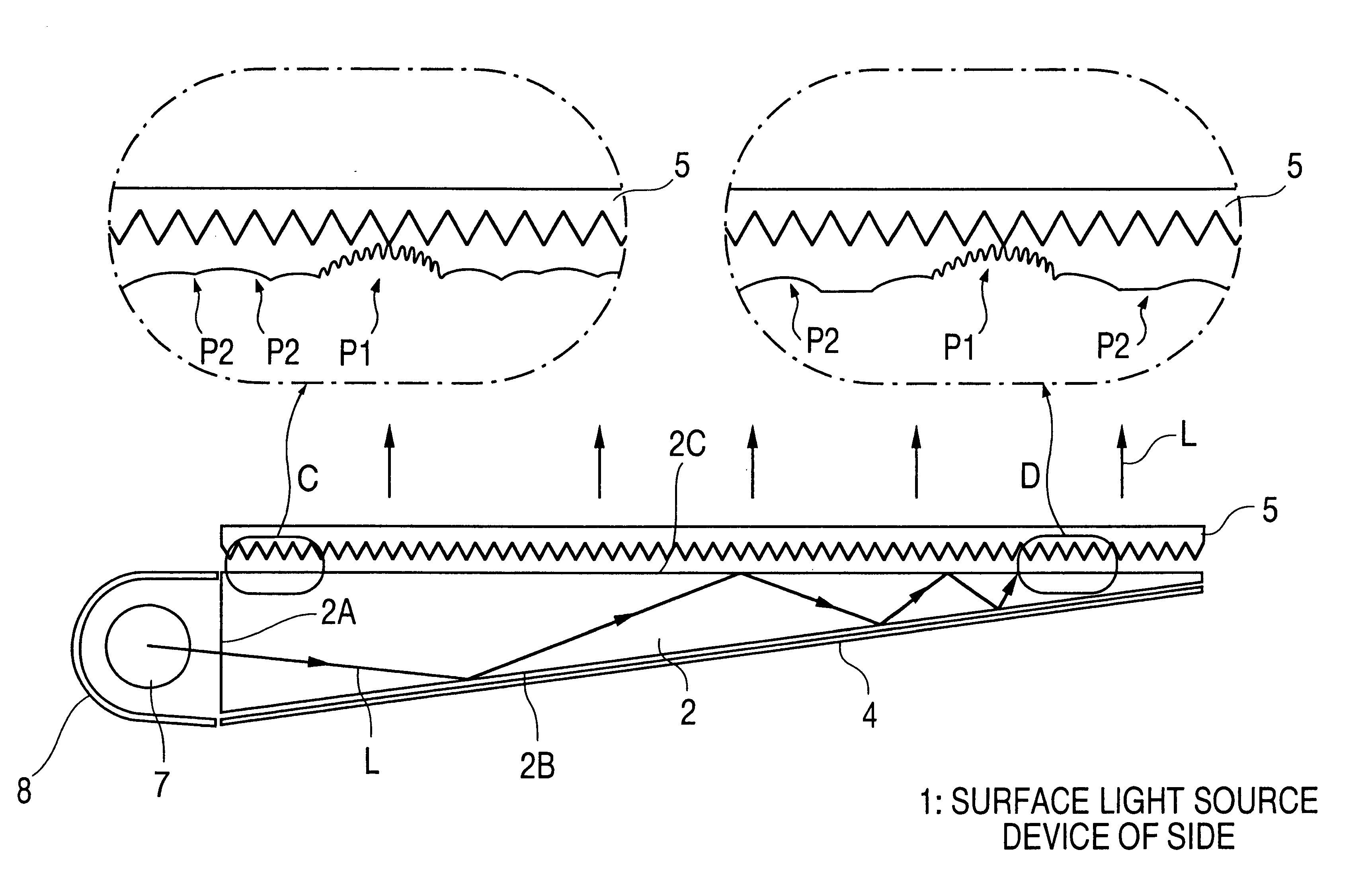
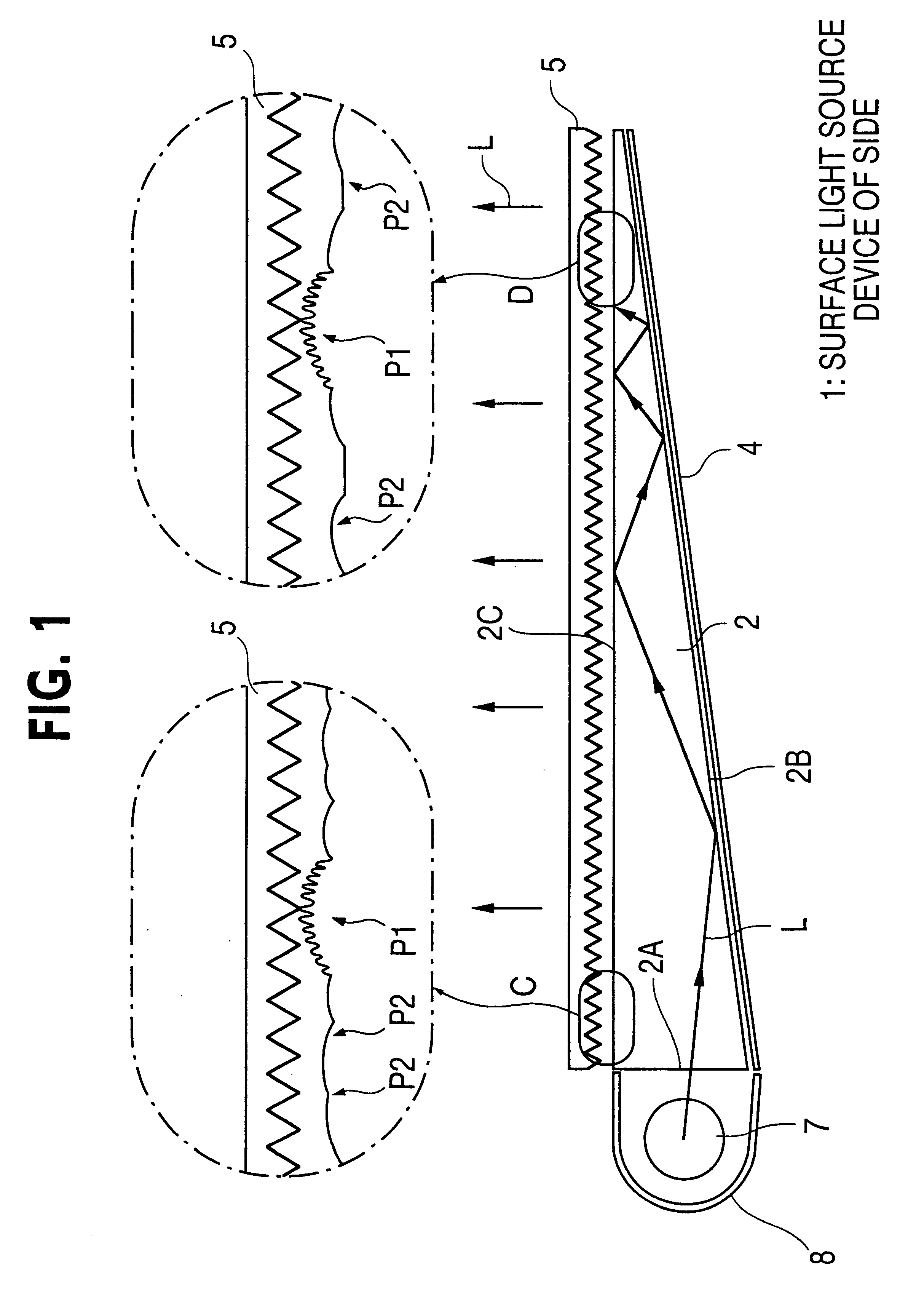
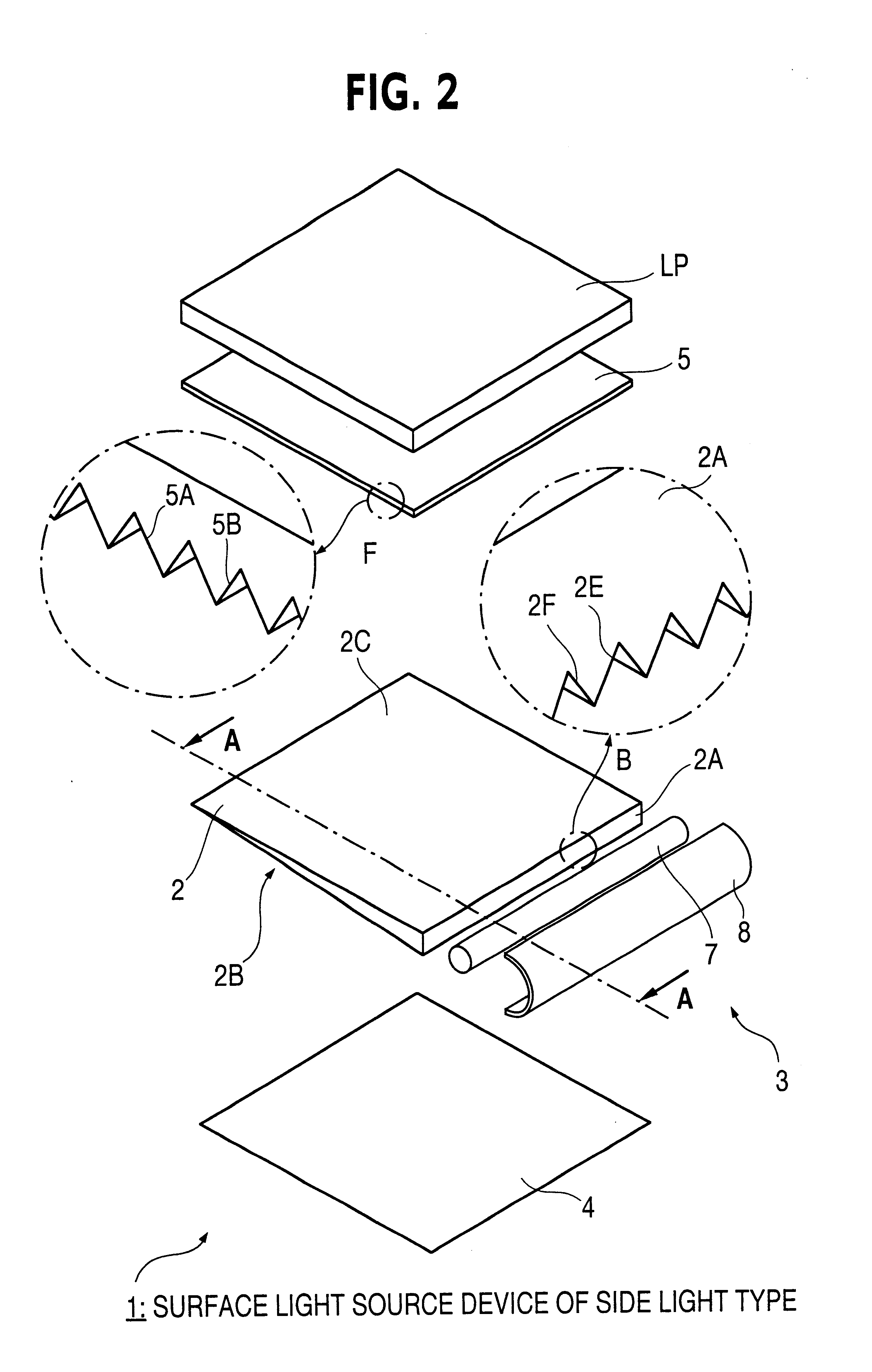
Referring FIG. 2, a liquid crystal display according to a typical embodiment of the present invention is shown in an exploded perspective illustration. The liquid crystal display includes a liquid crystal display panel LP and a surface light source device of side light type 1 arranged for illuminating the panel. Referring FIG. 1, a cross section view along line A--A in FIG. 2 to show the surface light source device of side light type 1.

As shown in both figures, the surface light source device 1 comprises a guide plate 2, a primary light source 3, reflection sheet 4 and a prism sheet 5. The reflection sheet 4, the guide plate 2 and the prism sheet 5 are laminatedly arranged in order. The primary light source 3 is arranged along an incidence face 2A provided by a minor face of the light guide plate 2. These elements are mounted and secured in a well-known manner on a frame not shown.

The primary light source 3 is composed of a cold cathode lamp (fluorescent lamp) 7 b...


PUM


Abstract

A surface light source device 1 for illuminating a liquid crystal display panel LP comprises a light guide plate 2, primary light source 3, reflection sheet 4 and prism sheet 5. First and second emission promotion regions P1, P2 are formed according to an intermingling distribution so that a major face of the light guide plate 2 provides an emission promotion face. Regions P2 are provided with a smaller emission promotion power as compared with that of regions P1. Ration of covering density of regions P1 to that of regions P2 is set as to vary depending on position in the emission promotion face. Regions P1 are shaped like dome projections tops of which are roughened. Regions P2 are shaped like dome projections or recesses surface of which are provided with a smoothness greater as compared with the surfaces of regions P2. Regions P2 are formed so that they cover among regions P1 without blank in the vicinity of an incidence face 2A to prevent edges from bringing reflective appearance. Distribution of anti regions P1 is set so that brightness distribution is flattened over the emission face 2C.

Description

1. Field of InventionThe present invention relates to a light guide plate, surface light source device of side light type and liquid crystal display. More specifically, the invention relates to a light guide plate having a minor face to provide a side end face through which light is inputted and having a major face through which light is outputted, and to a surface light source device of side light type and liquid crystal display which employ the light guide plate.2. Related ArtIt is known to apply a surface light source device of side light type to devices such as liquid crystal display in an backlighting arrangement of liquid crystal display panel. This arrangement is suitable for giving a thin whole structure to the device.In general, the surface light source device of side light type is provided with a primary light source such as a rod-shaped light source which is arranged beside a guide plate formed of, for example, a transparent resin light guide plate. Illumination light emi...

Claims


Application Information

Patent Timeline
IPC IPC(8): F21V8/00G02B27/00G02F1/1335G02F1/13F21Y103/00G09F9/00G02B6/00G02F1/13357G02F1/295
CPCG02B6/0036G02B6/0061G02F1/133615G02F1/295
Inventor OHKAWA, SHINGO
Owner ENPLAS CORP
Why Eureka
Try Eureka