

Method and device for determining the distribution of intensity and phase in a laser beam different cutting planes
a technology of intensity and phase, applied in the field of method and device for determining the distribution of intensity and phase in a laser beam different cutting plane, can solve the problems of not being able to achieve good results, competing with expensive commercially available systems, etc., and achieve the effect of increasing the field of application of the devi
Inactive Publication Date: 2002-01-15
COGEMA SA
View PDF2 Cites 5 Cited by
- Summary
- Abstract
- Description
- Claims
- Application Information
AI Technical Summary
Benefits of technology
Consequently, according to the invention, instead of moving to and fro among two cut planes, at least three cut planes are implemented and we proceed for instance from the first plane to the second one, then to the third one, . . . then to the Nth one, and we return to the first plane, and so on. The accuracy of the phase reconstruction on the intermediate planes is thus improved significantly, which allows to compete with expensive commercially available systems, e.g. of Hartmann-Shack or Zygo type.
Two versions of the method according to the invention are therefore proposed according to the calculation path among the measuring planes. The first methods covers the planes sequentially, whereas the second one performs a round-trip among plane pairs, and allows the relative weight of the different measured planes to be weighted.
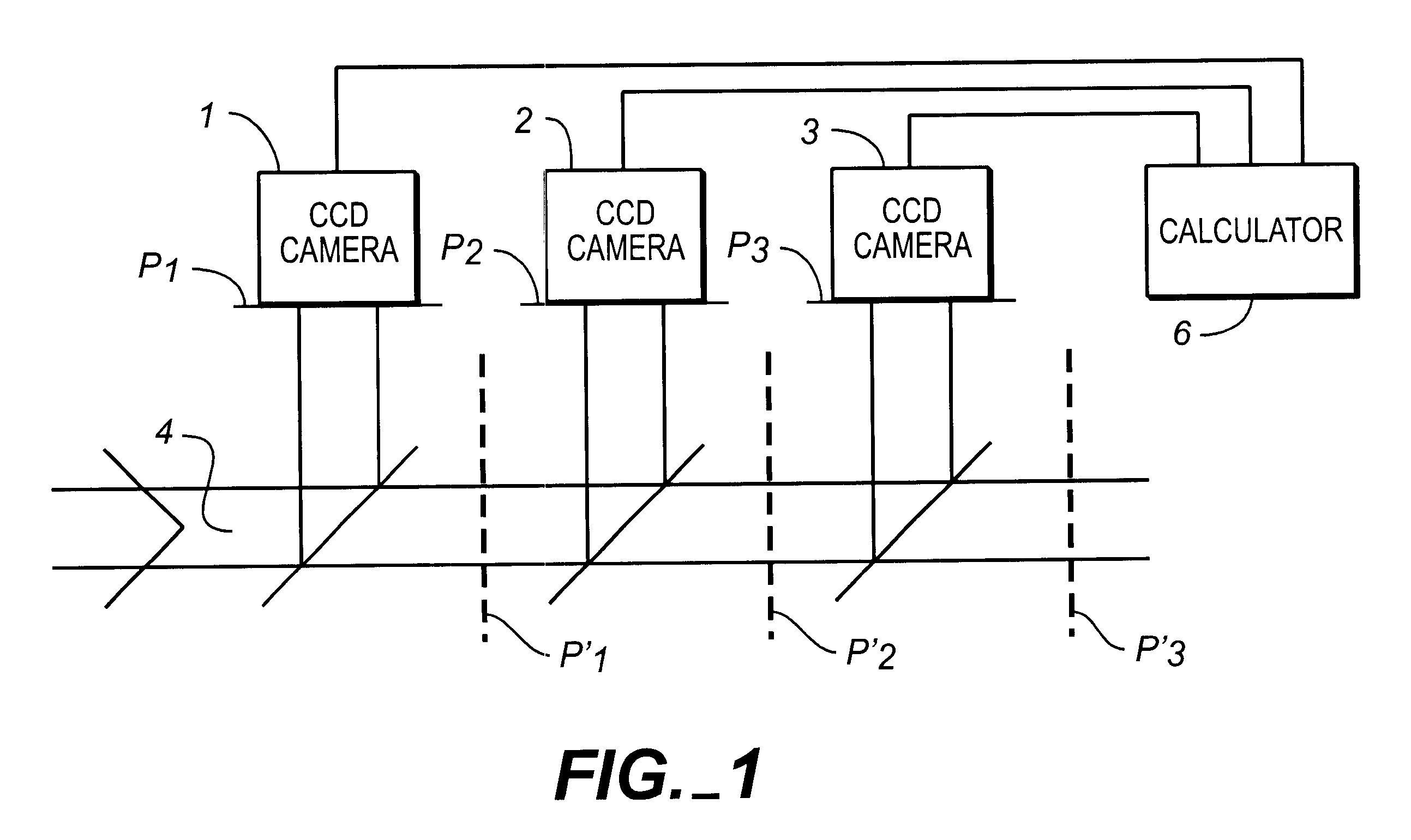
This device uses as many cameras as there are cut planes; preferably, the measured images are digitized before being processed. It can include a system for shaping the beam, limiting the extend thereof so as to adapt it to the cameras and to the bank length; a calibration step is then integrated in the steps of the main method. The addition of a lens or any other phase object allowing the beam to be adapted to the measuring device (divergence control . . . ) makes it possible to increase the field of application of the device. Using calculations, the calibration step then allows to do without the presence of the added component and thus to gain access to beam characteristics.
Problems solved by technology
Tests performed with laser beam images and these methods have not allowed to reach results sufficiently good to make it possible to do without systems of the Hartmann-Shack type.
The problem is therefore posed of finding a method and device allowing to improve the accuracy of phase reconstruction, and compete with expensive commercially available systems, e.g. of Hartmann-Shack or Zygo type.
Method used
View moreImage
Smart ImageViewing Examples

Examples
first embodiment
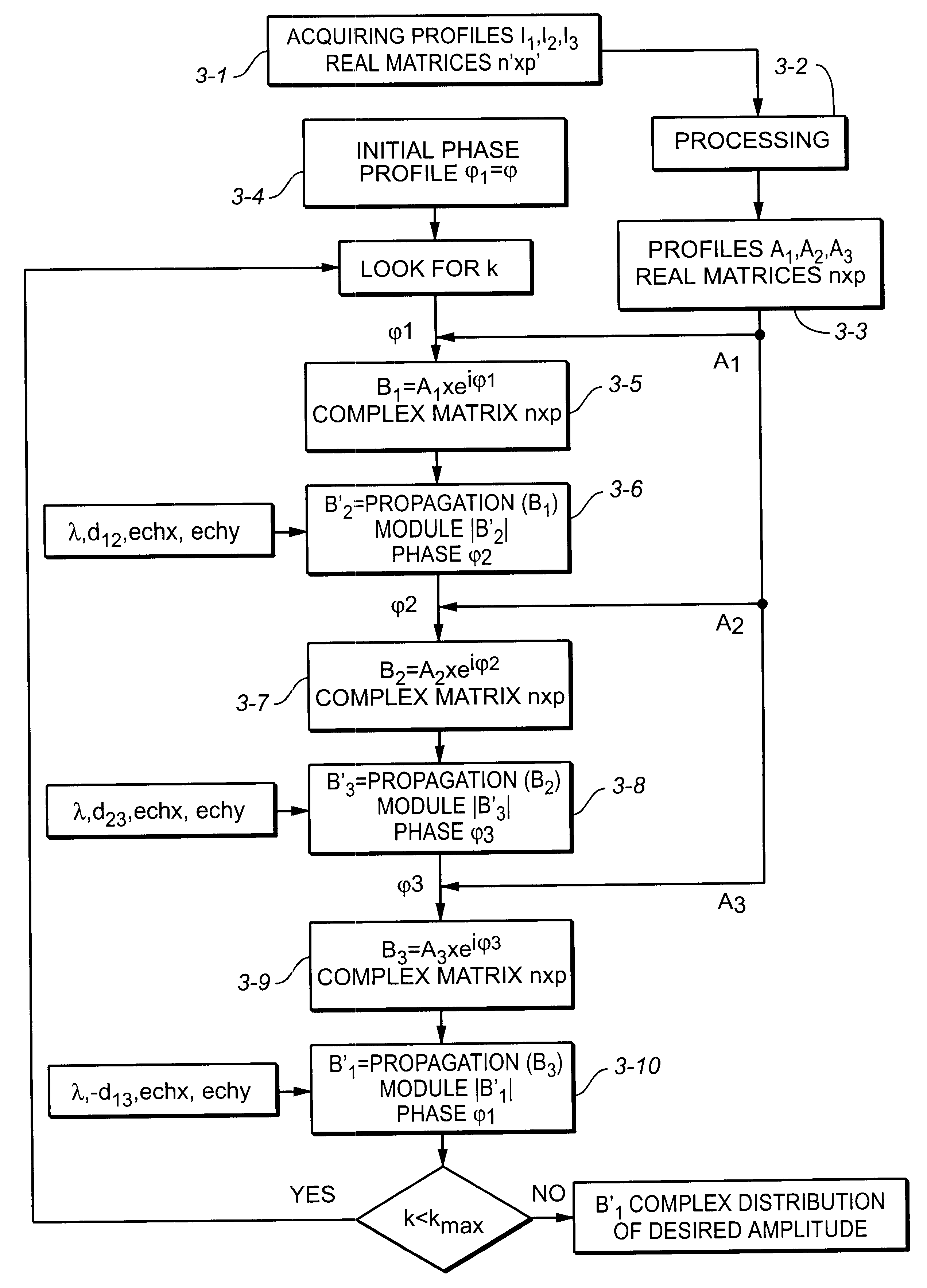
FIG. 3 represents the steps of a method according to the invention.
second embodiment
FIG. 4 represents the steps of a method according to the invention.
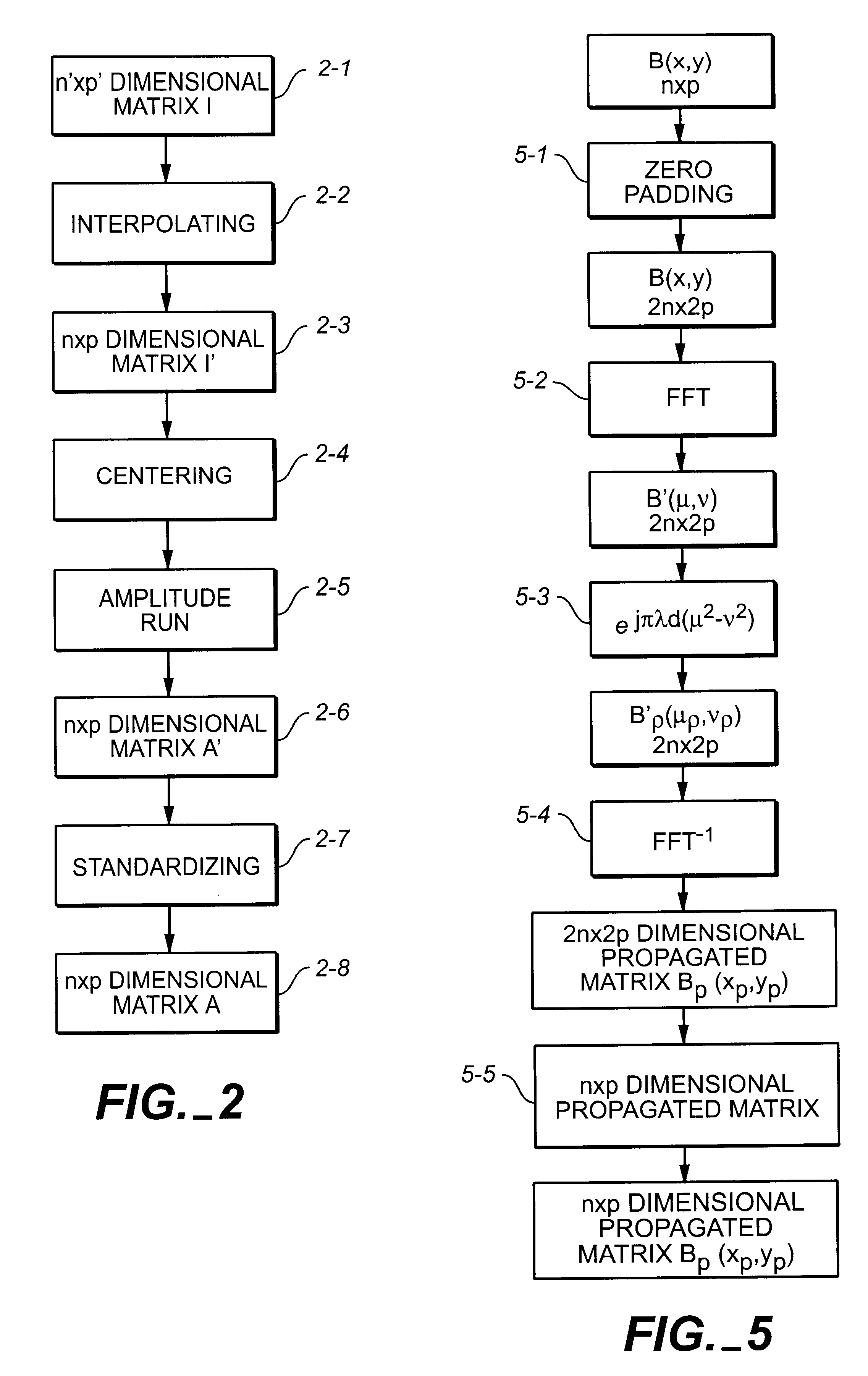
FIG. 5 schematically represents so-called propagation processing.
Login to View More PUM
 Abstract
A method and device for determining the intensity and phase distribution of a coherent light beam, in a plane, including measuring the intensity Ii, i=1 . . . N, of the beam, in N planes, N>=3, having the plane wherein intensity and phase distribution is to be determined, choosing, for plane i=1, an initial phase matrix phi1 and calculating a complex amplitude matrix, by term-wise multiplying the phase matrix eiphi1 by the corresponding amplitude matrix A1, for each plane j>1: determining a propagated complex matrix B'j from the measured amplitude matrix Aj-1 of plane j-1 and the phase matrix phi of plane j-1, extracting, from B'j, a phase matrix of plane j, and iterating the method up to convergence, with j=1 when j-1=N.
Description
TECHNICAL FIELD AND PRIOR ARTThe invention relates to a method and device for determining the intensity and / or phase distribution in various cut planes of a space coherent beam, in particular of the light beam produced by a laser.To carry out such a determination, known devices are split into three categories:1) interferometry devices,2) devices of Hartmann-Shack type3) space pattern sampling devices.Interferometry devices and methods use the combination of the wave front to be measured with a wave having a phase relation therewith.Devices and methods of the Hartmann-Shack type use a phase mask (lens arrays, holes . . . ) to evaluate the slope of the wave surface at each point. Reconstruction then allows the wave surface to be calculated.The problem of obtaining the phase from mere intensity profiles has already been studied in literature as the so-called "phase retrieval problem". The study of various existing solutions is proposed in the articles "Phase retrieval algorithms: a com...
Claims
Login to View More Application Information
Patent Timeline
 Patent Type & AuthorityPatents(United States)
IPC IPC(8): G01J1/42G01J9/00
CPCG01J9/00G01J1/4257G03H1/0866G03H2001/0816G03H2226/13
InventorBRUEL, LAURENTBELLEDENT, JEROME
OwnerCOGEMA SA