Device for adjusting distance of cutting blade from workpiece sheet

Inactive Publication Date: 2002-01-29
BROTHER KOGYO KK
View PDF20 Cites 61 Cited by
  • Summary
  • Abstract
  • Description
  • Claims
  • Application Information

AI Technical Summary

Benefits of technology

will become more apparent

Problems solved by technology

However, this configuration is extremely complicated and requires a great num

Method used


Image

  • Device for adjusting distance of cutting blade from workpiece sheet
  • Device for adjusting distance of cutting blade from workpiece sheet
  • Device for adjusting distance of cutting blade from workpiece sheet

Examples


first embodiment

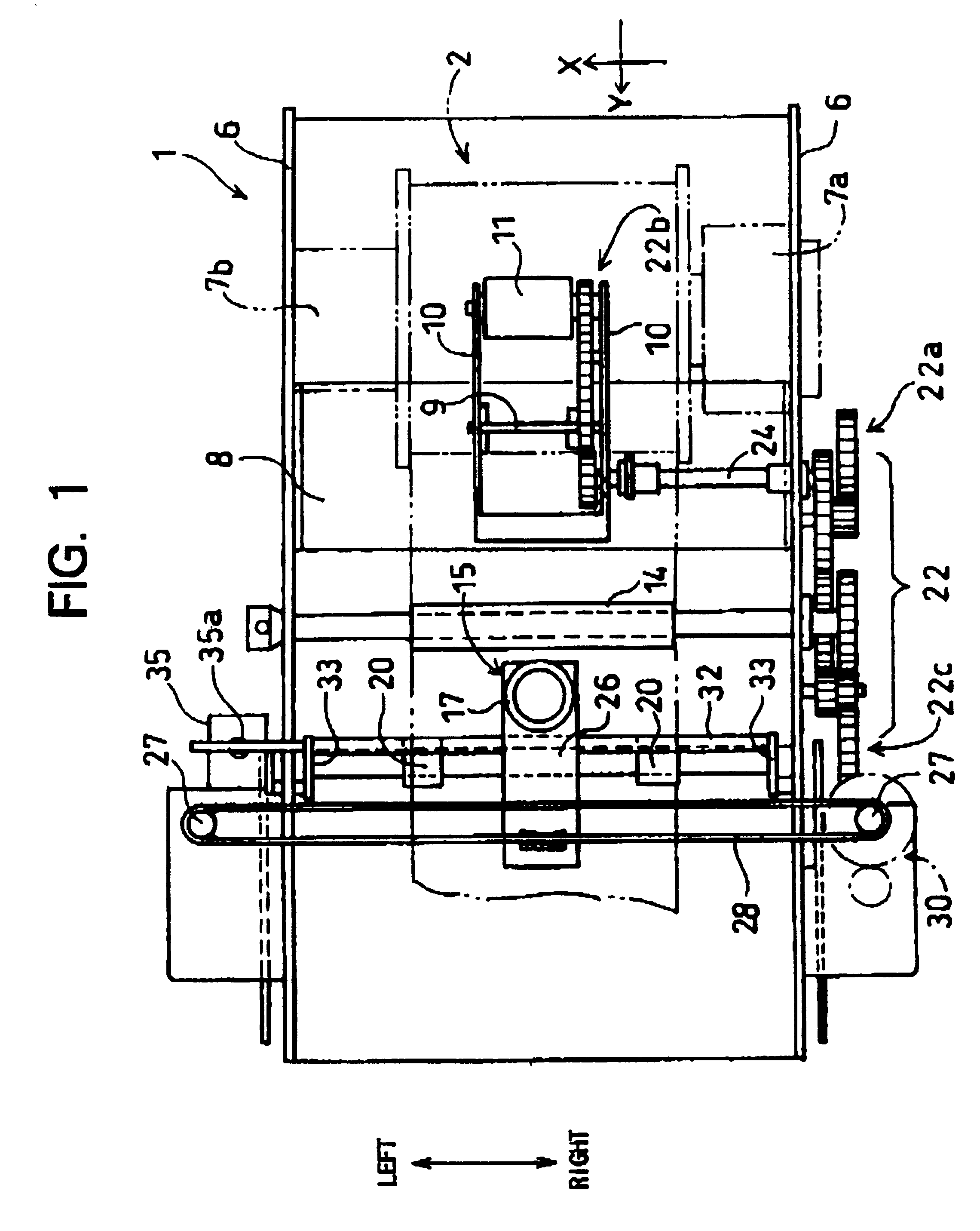
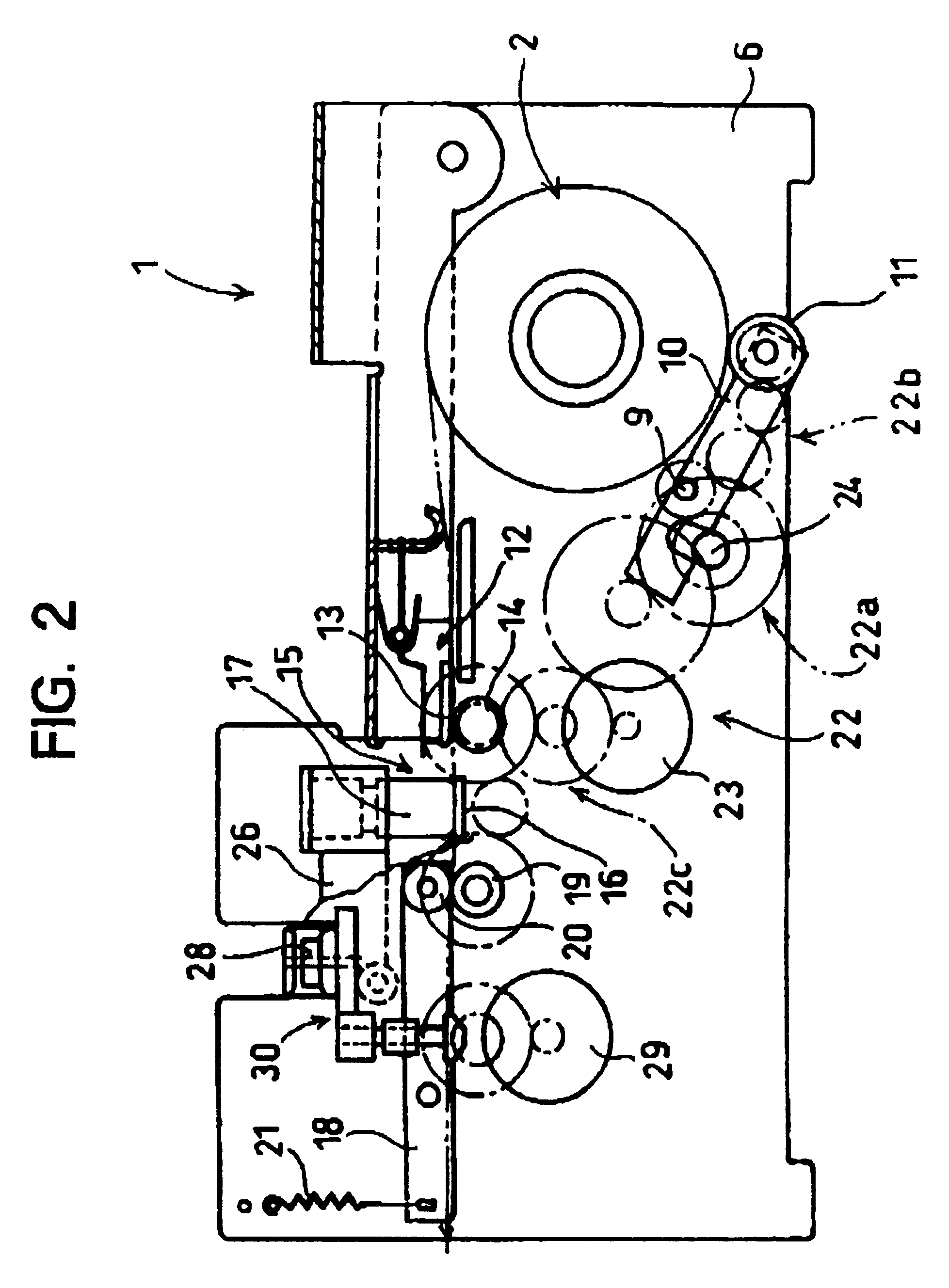
FIG. 1 is a plan view showing a tack sheet printing device 1 including a cutting portion 15 according to the present invention. FIG. 2 is a cross-sectional view of the printing device 1. FIG. 3 is a side view showing a mechanism for raising and lower a cutter holder of the cutter portion. FIG. 4 is a perspective view showing a roll sheet 2 of tack paper. FIG. 5 is a cross-sectional view of the cutter holder.

As shown in FIG. 4, the roll sheet 2 is used by the tack sheet printing device 1 as a workpiece to be cut. The recording sheet 3 is produced by coating an adhesive, such as a pressure sensitive adhesive, on the rear surface of a recording sheet, which is a band-shaped sheet of paper that can be printed on its surface. A band-shaped separation sheet 4 is then adhered onto the adhesive layer. Normally the roll sheet 2 is wound on a paper tube 5. The recording sheet 3 can also be formed from a gloss-coated paper or a synthetic resin film.

As shown in FIGS. 1 and 2, the tack sheet pri...

second embodiment

by moving the horizontal support body 60 to the inner rightward edge of a cutter holder 17', the cutter shaft 40 will be maximally raised up into the half cut position. On the other hand, by moving the horizontal support body 60 to the inner leftward edge of the cutter holder 17', the cutter shaft 40 will be maximally lowered into the full cut position. By stopping the upper edge of the cutter shaft 40 at a intermediate position along the slanting portion 61, the depth of the half cut can be adjusted to increase with a distance of the horizontal support body 60 in the leftward direction. Accordingly, the vertical position of the cutter shaft 40 can be adjusted linearly rather than in a step-like manner.

third embodiment

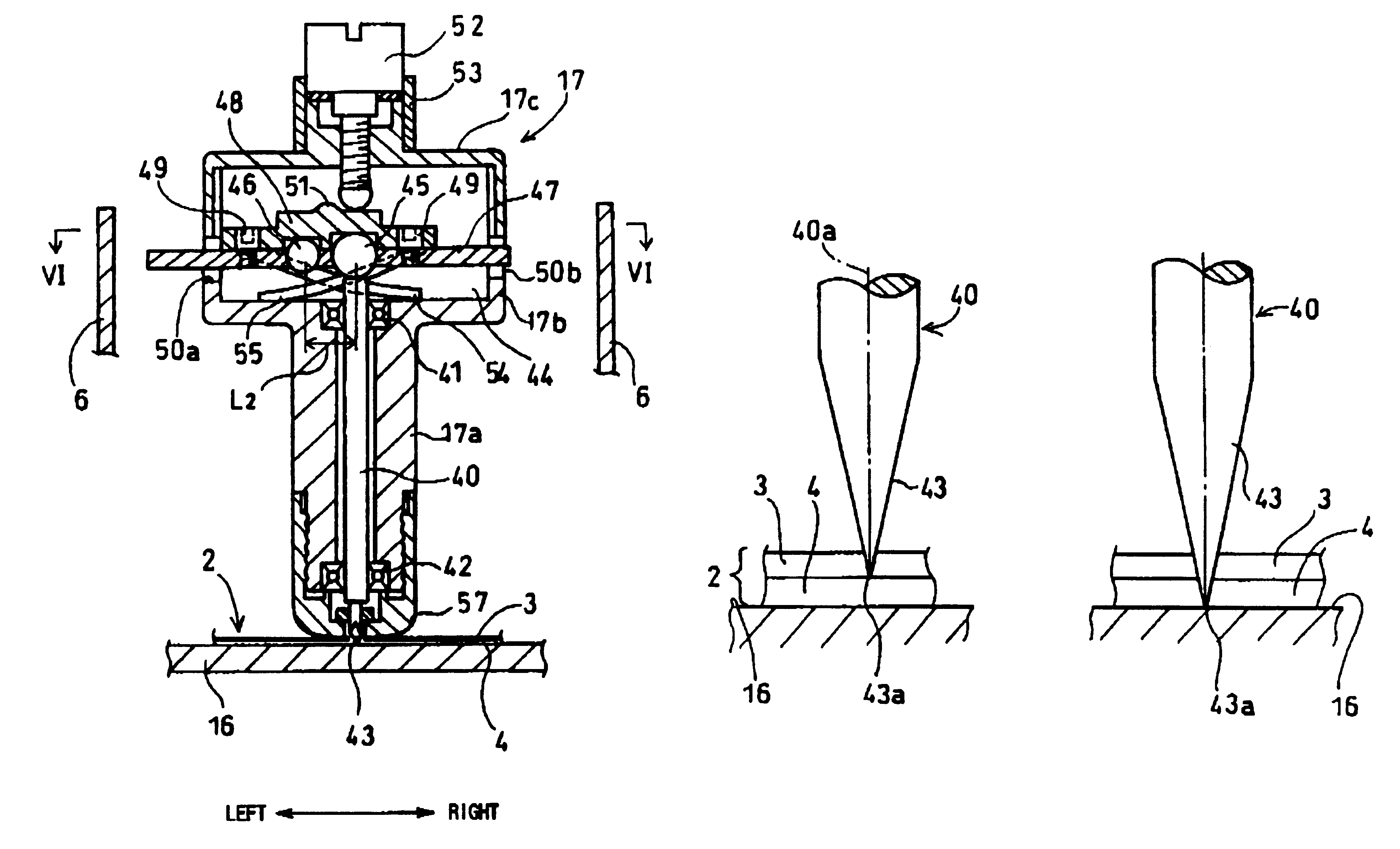
shown in FIGS. 9 and 10, a cutter shaft 40 of a cutter holder 172" is rotatably and vertically movably disposed in the guide cylinder portion 17a. A hollow case portion 17b is connected to the upper part of the guide cylinder portion 17a. A chamber 44 is defined by the hollow case portion 17b and a lid portion 17c, which covers the upper part of the hollow case portion 17b. The upper end (horizontal end surface) of the cutter shaft 40 is exposed in the chamber 44. A guide cylinder portion 63 is provided in the chamber 44. The lower peripheral surface of a selection body 62 is rotatably supported in the guide cylinder portion 63. The selection body 62 has an elongated round-rod shape and is for selecting a vertical position of the cutter shaft 40. A fitted body 64 is disposed in an indentation 65 formed in the lower surface of the lid portion 17c. The fitted body 64 has a substantial rectangular shape when viewed in a plan view, and so cannot be rotated, but is movable in the vertica...


PUM

PropertyMeasurementUnit
Diameteraaaaaaaaaa
Heightaaaaaaaaaa
Distanceaaaaaaaaaa

Abstract

A cutter shaft 40 provided with a cutter 43 as its lower tip is freely vertically movably disposed in a guide cylinder portion 17a of a cutter holder 17. A horizontal support body 47 is supported in a hollow case portion 17b. A large diameter first steel ball 45 and a small diameter second steel ball 46 are supported in the horizontal support body 47 separated by a suitable distance. The horizontal support body 47 supports the steel balls 45, 46 exposed from a lower end of the horizontal support body 47 but in a manner that prevents the steel balls 45, 46 from falling out of the horizontal support body 47. A cover body 48 is fixed on the upper surface of the horizontal support body 47 to prevent the first and second steel balls 45, 46 from moving in a vertical direction. The side edges of the horizontal support body 47 protrude from guide grooves 50a, 50b formed inside surfaces of the hollow case portion 17b. An adjustment screw screwingly engaged in a lid portion 17c presses downward on the cover body 48. On the other hand, resilient plate springs 54, 55 extending downward from the cover body 48 urge the cover body 48 upward.

Description

The present invention relates to a device for adjusting vertical position of a cutter, to enable half cut or full cut in label sheets, wallpaper sheets, strip coat sheets, and the like following an optional direction.RELATED ARTJapanese Utility-Model Application Publication No. HEI-2-14952 discloses an example of a conventional device for adjusting vertical position of a cutter. The device has two electromagnetic solenoids for selectively adjusting the cutter between an uppermost position, wherein the workpiece is not cut at all, a half cut position, and a full cut position.The device is provided with a head capable of movement in X and Y directions of a horizontal plane. An outer cylinder is rotatably disposed on the head. A shaft with a cutting blade at its lower end is mounted in a guide tube in the outer cylinder, capable of free vertical movement. A gear is fixed to the outer surface of the outer cylinder. The direction in which the cutting blade faces can be changed by rotatin...

Claims


Application Information

Patent Timeline
IPC IPC(8): B41J11/70B26D7/26B26D3/08B26F1/38B26D5/00
CPCB26F1/3813B41J11/70B26D7/26B26D7/2628B26D3/085B26D2007/2678Y10T83/0333Y10T83/949Y10T83/0348Y10T83/9486
Inventor HIRAHATA, SHINICHIOGAWA, YASUHIROCHIKAMOTO, TADANOBUMINAMINAKA, KAZUYOSHI
Owner BROTHER KOGYO KK
Why Eureka
Try Eureka