Adaptive motion vector detecting apparatus and method

Inactive Publication Date: 2002-01-29
SONY CORP
View PDF5 Cites 15 Cited by
  • Summary
  • Abstract
  • Description
  • Claims
  • Application Information

AI Technical Summary

Benefits of technology

An object of the invention, therefore, is to eliminate a mismatch between the check block and the reference b

Problems solved by technology

A problem exists, however, that the motion vector detecting circuit 101 may generate an erroneous motion vector.
However, when the search block making up the check block has a very different pattern as, for example, shown by FIG. 11C, the

Method used


Image

  • Adaptive motion vector detecting apparatus and method
  • Adaptive motion vector detecting apparatus and method
  • Adaptive motion vector detecting apparatus and method

Examples


first embodiment

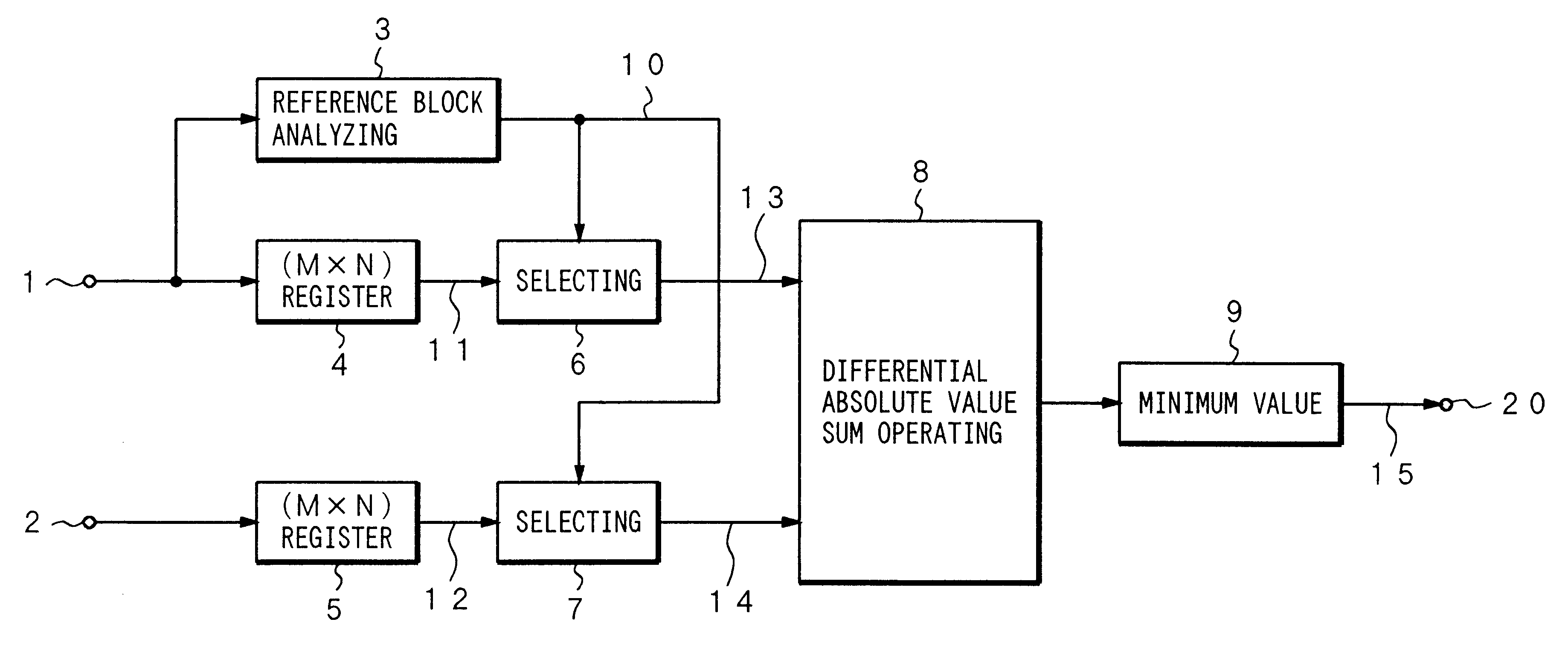
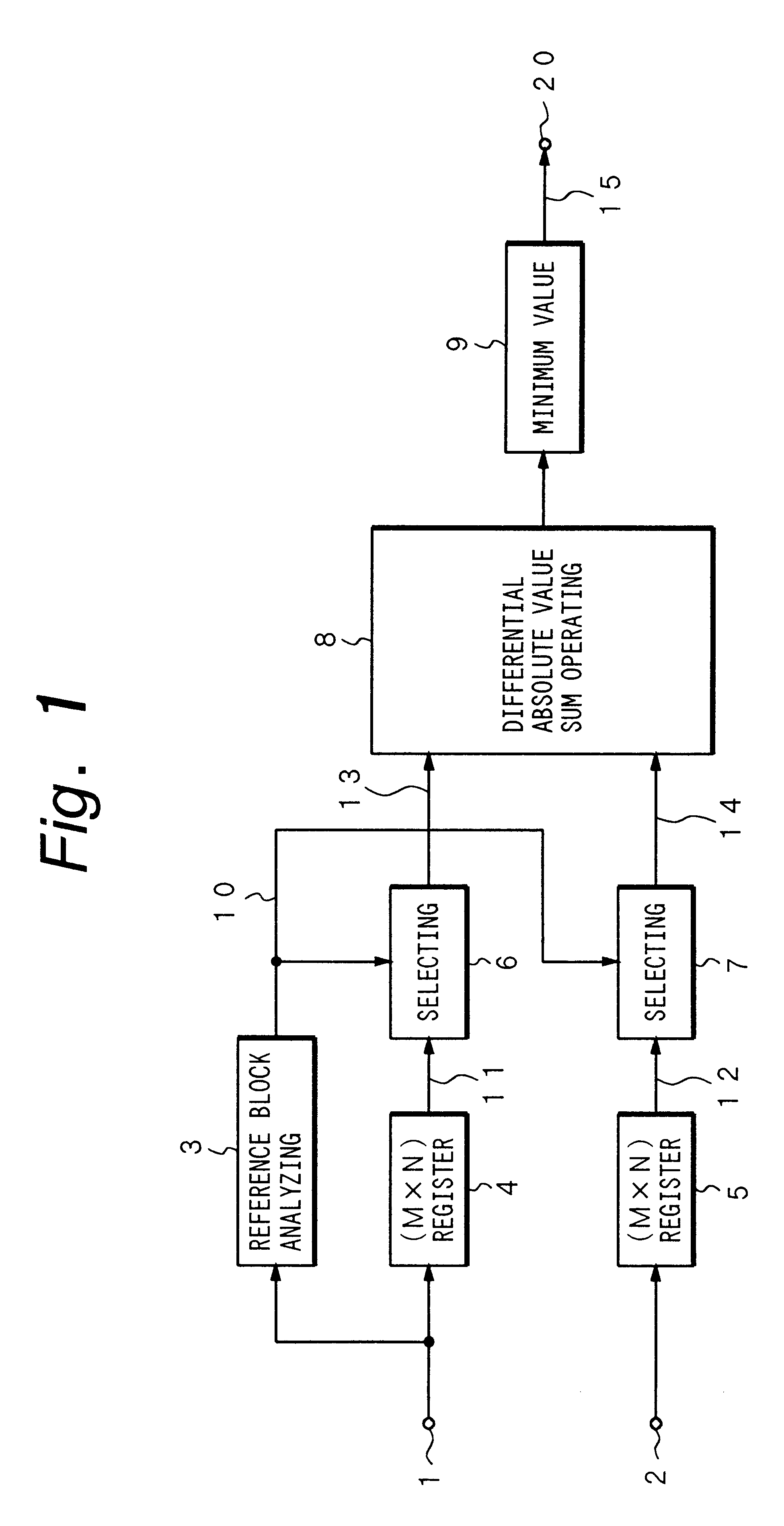
the invention will be described with reference to the motion vector detecting circuits of FIGS. 1 and 2. In FIG. 1, the motion vector detecting circuit receives reference and check block data from input terminals 1 and 2, respectively. The blocks are stored by registers 4 and 5. A reference block analyzing circuit 3 commands selecting circuits 6 and 7 to adaptively select pixels of each block. The selected pixels are forwarded to a differential absolute value sum operating circuit 8 which calculates the residual difference. A minimum value circuit 9 selects the minimum residual difference because the correct check block should have a minimum difference between successive frames and the correct residual difference is output.

The adaptive selection operation of the motion vector detecting circuit will now be described in more detail. The reference block data is supplied to the input 1 and forwarded to both the reference block analyzing circuit and the (M.times.N) register 4. The check ...

second embodiment

The second embodiment will now be described with reference to FIGS. 3, 4A to 4C, 6, 7A and 7B. FIG. 3 is a representation of pixels in a 4.times.4 block. According to the second embodiment, adaptive sampling is achieved by dividing the blocks into sub blocks 30 and 31 (here, two 4.times.2 sub blocks) and determining the maximum and minimum pixel values for each sub block.

FIG. 4A, for example, shows the reference block 40 divided into two 4.times.2 sub blocks 41 and 42. The extracted maximum pixel values (a and b) in each sub block are shown by the hatched circles while the extracted minimum values in each sub block are indicated by the dotted circles (c and d). Similarly, the check block 43 of FIG. 4B is divided into two sub blocks 44 and 45 and the extracted maximum and minimum values are indicated by the circles (a', b', c' and d'). The extracted values are sent to a differential absolute value sum operating circuit 61 (FIG. 6) and the residual difference is calculated therefrom. ...


PUM


Abstract

An adaptive motion vector detector adaptively selects the pixels employed in detecting motion vectors between a first frame and a second frame of a video broadcast. The first frame includes a reference block of pixels and the second frame includes a check block of pixels. An analyzing circuit adaptively determines positions of a first subset of pixel values in the reference block based on a variable feature of the reference block. A selecting circuit samples the first subset of pixel values in the reference block and a second subset of pixel values in the check block at the positions determined by the analyzing circuit.

Description

The present invention relates to motion vector detecting and, more particularly, to adaptive motion vector detecting.Motion vector detecting is employed in an MPEG system, which was developed in accordance with standards established by the Motion Picture Experts Group (MPEG). The MPEG system provides encoding and decoding of a high-definition television broadcast which minimizes the amount of transmitted data. Motion vectors designate the direction and magnitude of change of an image block comprising part of an individual frame in the television broadcast. By defining all image blocks of the frame in terms of motion vectors instead of individual pixels, the MPEG system can reduce the amount of data required to be broadcast. Such a system is known as interframe predictive encoding system because the motion vectors are employed to determine differences between different frames.As shown in FIG. 8, a predictive encoding apparatus receives a current frame of a television picture at input...

Claims


Application Information

Patent Timeline
IPC IPC(8): H04N7/26H04N19/105H04N11/04H04N19/134H04N19/136H04N19/137H04N19/167H04N19/176H04N19/196H04N19/50H04N19/503H04N19/51H04N19/557H04N19/60H04N19/61H04N19/625
CPCH04N19/53H04N19/51
Inventor OGURA, EIJI
Owner SONY CORP
Why Eureka
Try Eureka