High toughness steel and a method for manufacturing the same

a technology of high toughness steel and manufacturing method, which is applied in the field of high toughness steel and a manufacturing method for the same, can solve the problems of increasing the energy required for a grain boundary fracture, brittle fracture, and grain boundary fracture,

Inactive Publication Date: 2002-02-19
NATIONAL RESEARCH INSTITUTE FOR METALS SCIENCE AND TECHNOLOGY AGENCY
View PDF2 Cites 15 Cited by
  • Summary
  • Abstract
  • Description
  • Claims
  • Application Information

AI Technical Summary

Problems solved by technology

In a steel material which has been utilized as the steel for structural purposes, there is a problem that a prior-austenite grain boundary which is the weakest part or the inherent austenite grain boundary prior to conducting a mechanical process and a thermal treatment is broken whereby intergranular cracking is resulted and that a brittle fracture takes place.
For example, in the case of a tempered martensite steel, filmy carbides precipitate continuously in an a prior-austenite grain boundary and they restrict the plastic deformation near the grain boundary resulting in such a fracture in the grain boundary.
However, with an increase of the area, energy which is required for a grain boundary fracture can be increased and, in addition, a geometrical burden can be formed against the brittle cracking extending at the resistance prior-austenite grain boundary.
Said boundary temperature is called a ductile-brittle transition temperature and, when said temperature is low...

Method used


Image

  • High toughness steel and a method for manufacturing the same
  • High toughness steel and a method for manufacturing the same
  • High toughness steel and a method for manufacturing the same

Examples


example 1

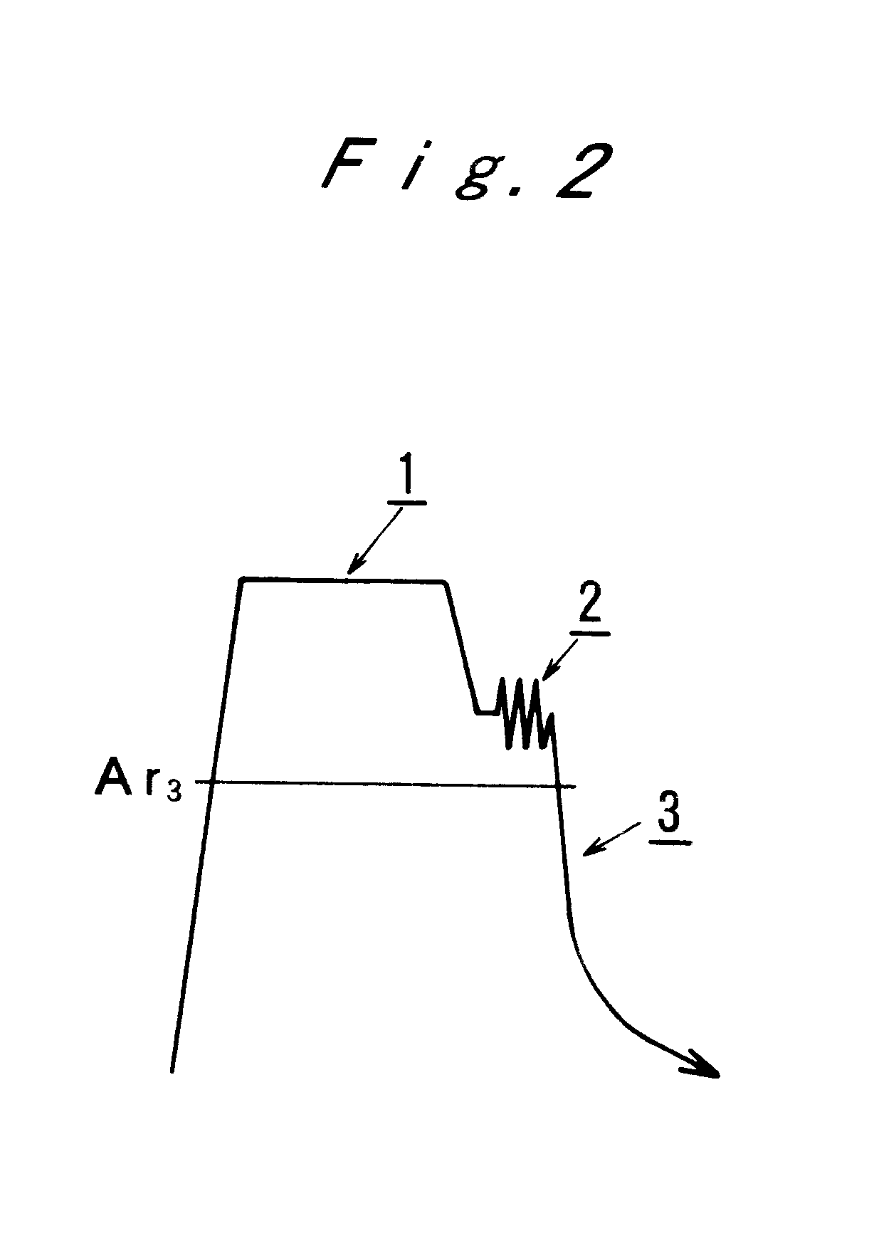
Steel having a composition of Fe, 0.35% of C, 1.5% of Mn and 0.5% of Si in terms of % by weight was made into martensite by the process consisting of the following steps of a-c.

a. heated by electricity at the rate of 5.degree. C. / second up to 1,100.degree. C.;

b. kept at 1,100.degree. C. for 60 seconds;

c. cooled down to 700.degree. C. at the rate of 10.degree. C. / second;

d. subjected to an anvil compressing to 50% at 10 / second; and

e. cooled with water.

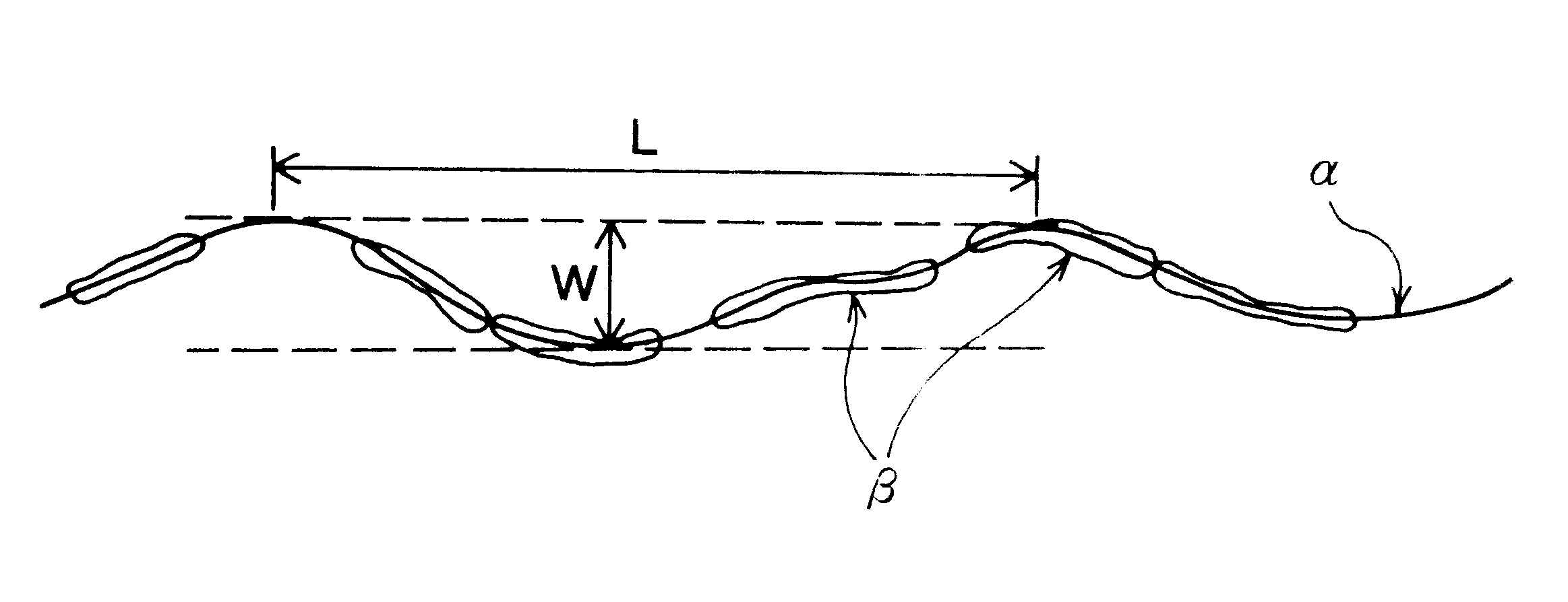
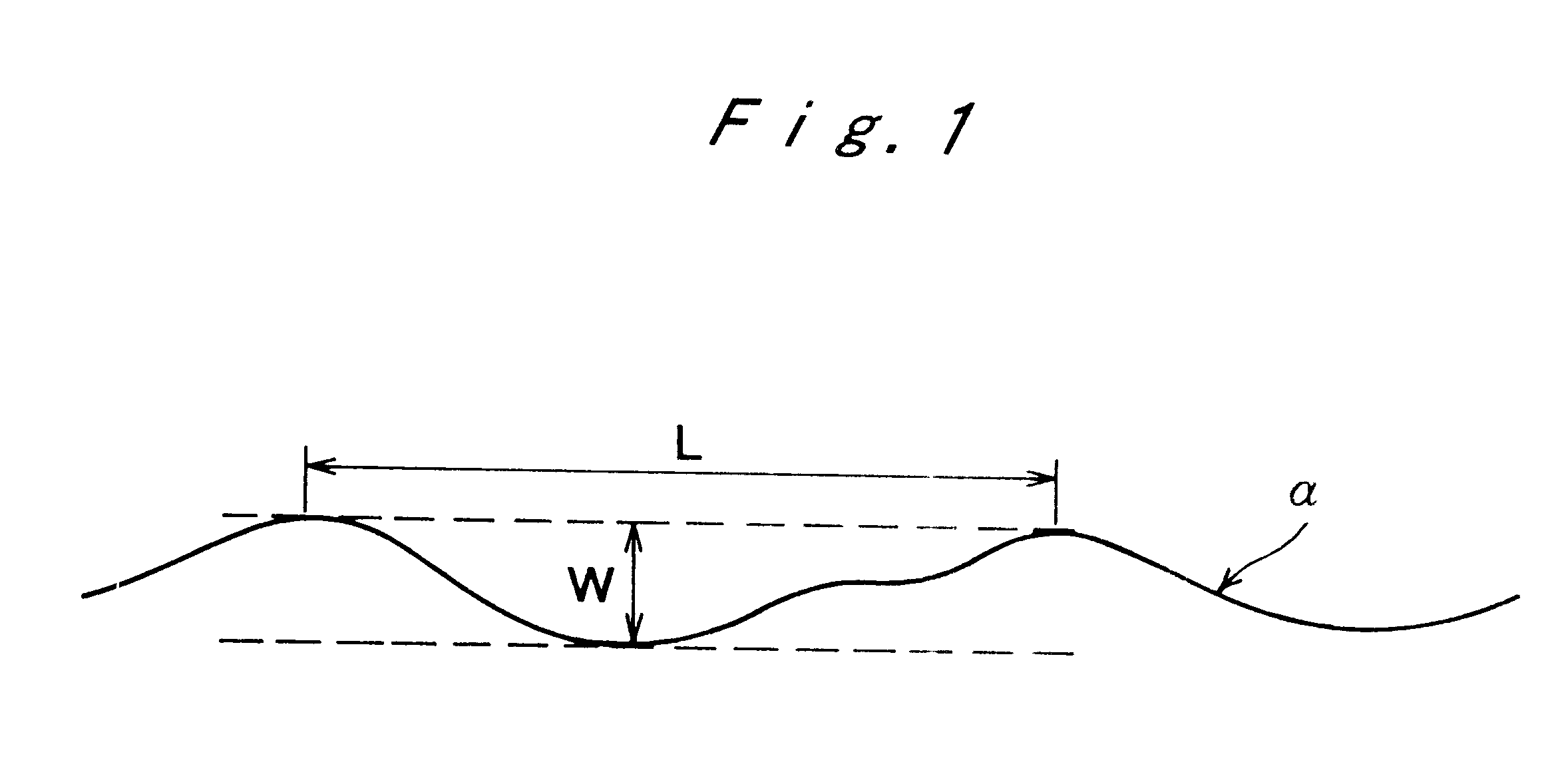
As shown in FIG. 6, in the resulting steel, the areas of not less than 90% of the prior-austenite grain boundary seen from a vertical plane had fine wavy ups and downs. Each cycle and amplitude of said ups and downs were not more than 2 .mu.m and not less than 400 nm, respectively.

Incidentally, the prior-austenite grain boundary is the area as shown by an arrow in FIG. 6.

Tensile strength of the resulting steel was 1,397 MPa while ductile-brittle transition temperature thereof was 0.degree. C.

example 2

A tempered martensite steel having a composition of Fe, 0.35% of C and 2.0% of Mn in terms of % by weight was manufactured by 3 process consisting of the following steps a-h.

a. heated by electricity at the rate of 5.degree. C. / second up to 1,100.degree. C.;

b. kept at 1,100 .degree.C. for 60 seconds;

c. cooled down to 750.degree. C. at the rate of 10.degree. C. / second;

d. subjected to an anvil compressing to 50% at 10 / second;

e. cooled with water;

f. subjected to an induction heating at the rate of 200.degree. C. / second up to 450.degree. C.;

g. kept at 450.degree. C. for 15 seconds; and

h. cooled at the rate of about 50.degree. C. / second by blowing with He.

As shown in FIG. 8, in the resulting steel, prior-austenite grain boundary and its triple point which are noted in the conventional tempered martensite steel were not confirmed.

Further, as shown in FIG. 9, the prior-austenite grain boundary had fine wavy ups and downs when seen from a vertical plane. Each cycle and amplitude of said ups ...


PUM

PropertyMeasurementUnit
Lengthaaaaaaaaaa
Fractionaaaaaaaaaa
Fractionaaaaaaaaaa

Abstract

Ups and downs having a cycle of not more than 5 mum and an amplitude of not less than 200 nm are formed in a part of not less than 70% per unit length of a prior-austenite grain boundary which is observed in a linear form when seen from a vertical plane by a series of steps of subjecting a steel in a state of austenite to a deformation in not less than 30% of a total area reduction rate at a temperature region which is lower than recrystallization temperature of austenite, and subsequently cooling a deformed steel without causing neither recrystallization nor phase transformation of a diffusion type.

Description

The invention of this application relates to a high toughness steel and to a method for manufacturing the same. More particularly, the invention of this application relates to a high toughness steel having an excellent toughness useful for a steel material used as steel for structural purposes such as steel bars, section steel, thin plates and thick plates and also relates to a method for manufacturing the same.DESCRIPTION OF THE PRIOR ARTIn a steel material which has been utilized as the steel for structural purposes, there is a problem that a prior-austenite grain boundary which is the weakest part or the inherent austenite grain boundary prior to conducting a mechanical process and a thermal treatment is broken whereby intergranular cracking is resulted and that a brittle fracture takes place.For example, in the case of a tempered martensite steel, filmy carbides precipitate continuously in an a prior-austenite grain boundary and they restrict the plastic deformation near the gra...

Claims


Application Information

Patent Timeline
IPC IPC(8): C22C38/04C21D7/00C21D8/00C21D7/13
CPCC21D7/13C22C38/04C21D8/00C21D2201/00
Inventor YUSA, SATORUTSUZAKI, KANEAKITAKAHASHI, TOSHIHIKO
Owner NATIONAL RESEARCH INSTITUTE FOR METALS SCIENCE AND TECHNOLOGY AGENCY
Why Eureka
Try Eureka