
Bullet-proof vest with distress signaling system

a technology of distress signaling and bulletproof vest, which is applied in the direction of instruments, nuclear elements, nuclear engineering, etc., can solve the problems of severe, even deadly injury to the wearer, and not perfectly effective, and is less common

Inactive Publication Date: 2002-02-19
FORD SEAN
View PDF13 Cites 132 Cited by
  • Summary
  • Abstract
  • Description
  • Claims
  • Application Information

AI Technical Summary

Benefits of technology

It is an object of the present invention to provide a bullet proof vest which will signal a central station when the wearer is subjected to a substantial impact, such as from a bullet.
It is another object of an aspect of the invention to provide a bullet proof vest which will perceive the location of the wearer and will forward the location to the central station when the wearer has received a substantial impact.
It is another object of the invention to provide a vest which will distribute the impact of a trauma over a large portion of the wearer's body, will signal a central station that the impact has been delivered, and will identify the wearer and his location.
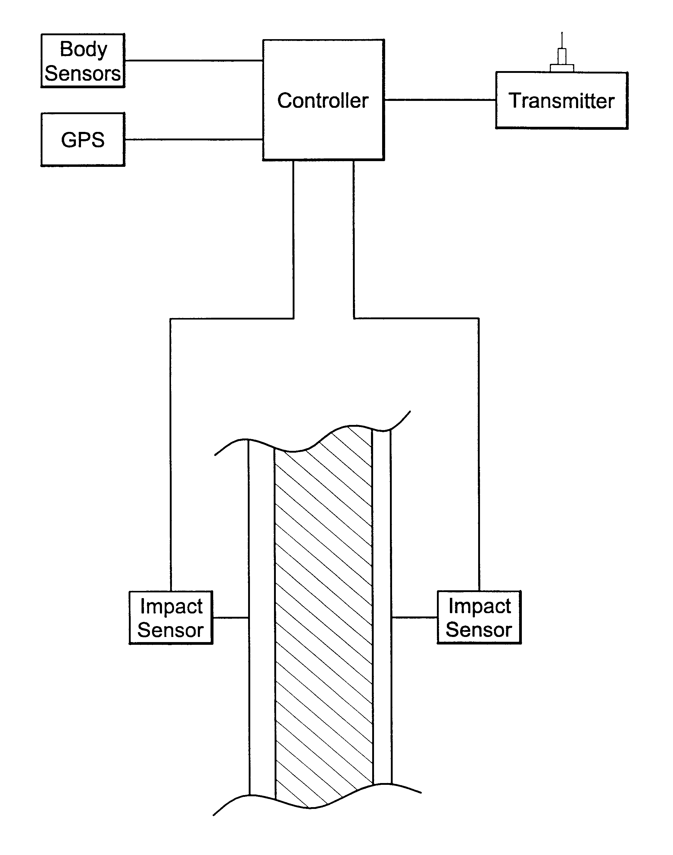
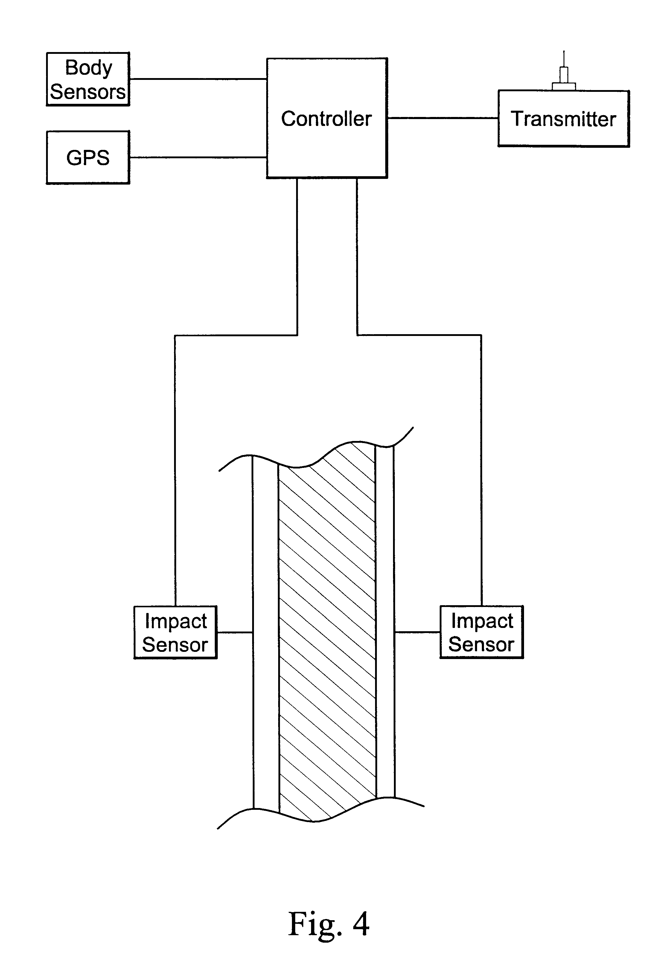
It is another object of an aspect of this invention to provide a vest which can reduce the effect of an impact on the wearer while monitoring the wearer's bodily functions. Should the wearer be subjected to an impact or should the bodily functions move beyond a predetermined range, a transmitter will send a distress signal to a central station identifying the wearer and his location.

Problems solved by technology

Rigid plates can also be employed but due to their added weight and discomfort, they are less common.
Although these vest are often successful at preventing or reducing the wearer's injuries, they are not perfectly effective.
Further, even when the bullet does not pass completely through, the impact from stopping the bullet can be substantial, causing severe, even deadly injury to the wearer.
Once the wearer has been injured, he may be unable to request aid.
Consequently, although the vest may reduce injury, the officer is still at great risk and not easily located to receive aid even if it is known that the officer is injured.
While such officers typically carry radios, if the officer is unconscious or delirious, he may not be able to instruct anyone as to his location.
The problems arising in these situations are not even recognized in the prior art, let alone resolved.
Again, there is no teaching to use this system with a bullet proof vest or with an impact sensing device.

Method used


Image

  • Bullet-proof vest with distress signaling system
  • Bullet-proof vest with distress signaling system
  • Bullet-proof vest with distress signaling system

Examples


Embodiment Construction

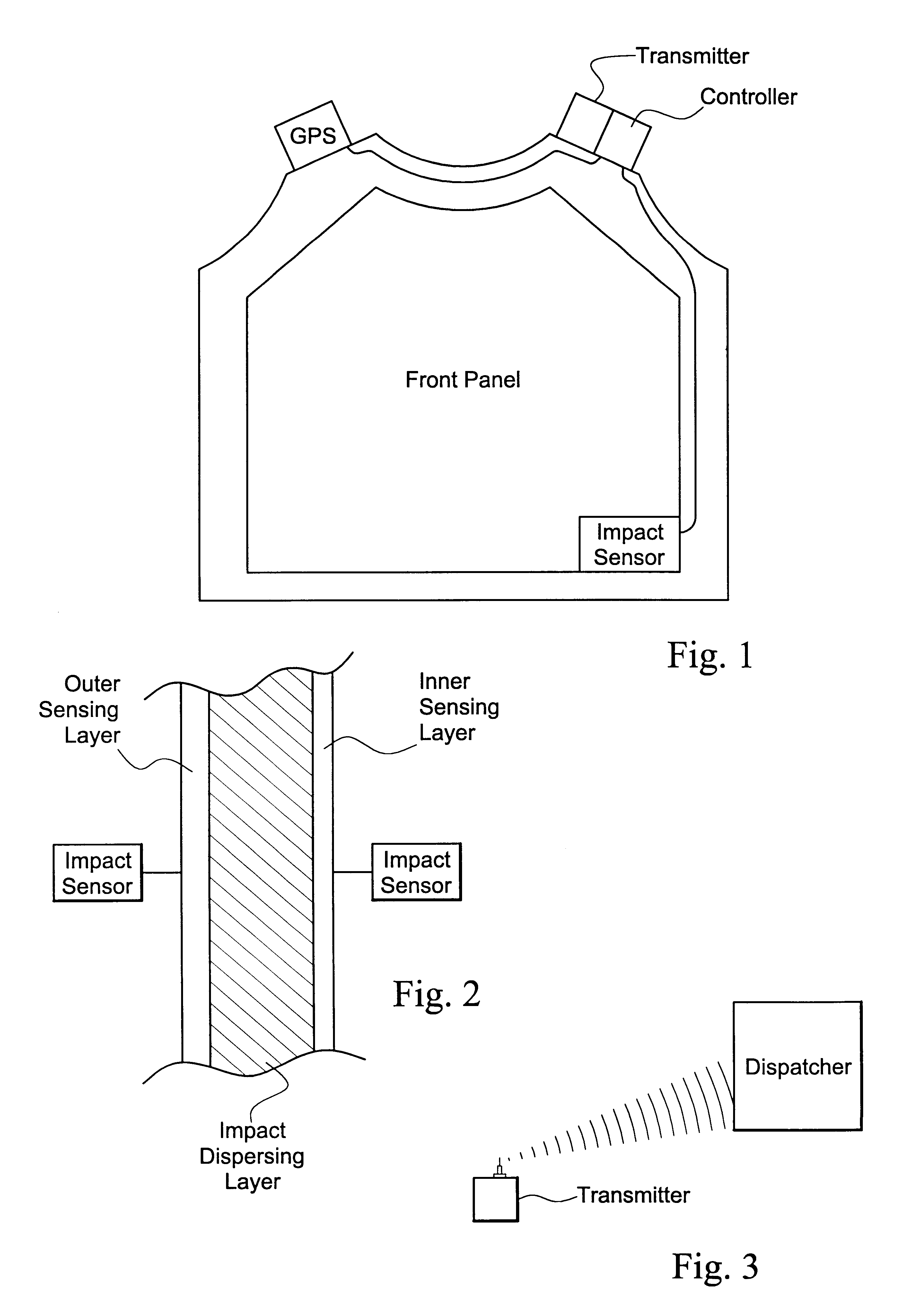
Referring to FIG. 1, the instant invention relates to a garment. The garment can have any shape but is currently preferred to be a vest. One skilled in the art will appreciate that the invention can be implemented in a coat, bid, pants, cape, shield, etc., and still practice the invention. The vest has a front panel and a rear panel connected by a yoke. Straps can be employed to secure the front panels and the rear panels in place on the wearer's body. Of course, leg panels and the like can be provided to cover more of the wearer's body, if desired.

Each panel of the garment preferably has three layers. These layers can be distinct and simply attached together. Alternatively, these layers can be integrally formed or covered with a washable sleeve. The first or outer layer of the garment is a pressure sensing layer. As currently preferred, the pressure sensing layer may be made of a piezoelectric material. As such, when the material is subjected to an impact, it will provide a current...


PUM


Abstract

A garment having at least one layer providing bullet-proof protection for the wearer. One or more additional layers incorporate sensors to detect the magnitude of an impact to generate a signal activating a wireless transmitter to send distress signals and / or positional and other information to a remote base location. Additional sensors may be provided to indicate physical characteristics of the wearer.

Description

The present invention relates to bullet-proof vests and more particularly to such vests having the capability of selectively providing distress and warning signals to remote locations.This invention is related to the field of personal security devices. In particular, the invention is directed to a protective garment, such as a vest, which will not only provide protection against traumas and impacts delivered to the wearer, but will provide a distress signal to a police station or other such authority when the trauma or impact is received.It is common for police officers and other peace keeping officials to wear protective vests. These vests are made of a bullet proof material and additional shock absorbing material. Kevlar.RTM. or other tightly woven, tear resistant material can be employed as the bullet proof material. Rigid plates can also be employed but due to their added weight and discomfort, they are less common. Padding, including inflatable chambers or compressible fill, ca...

Claims


Application Information

Patent Timeline
Patent Type & Authority Patents(United States)
IPC IPC(8): A41D1/00F41H1/00F41H1/02H04B1/38H04B1/02H04B1/034
CPCH04B1/385H04B1/0343F41H1/02A41D1/002
Inventor FORD, SEAN
Owner FORD SEAN
Learn More