Electrical integrated modular power node

Inactive Publication Date: 2002-02-26
L 3 COMM SPD TECH
View PDF30 Cites 23 Cited by
  • Summary
  • Abstract
  • Description
  • Claims
  • Application Information

AI Technical Summary

Problems solved by technology

As a result, each node typically takes on its own identity and is not thereafter easily changed.
This means the power distribution system which eventually results loses flexibility early in the design process fo

Method used


Image

  • Electrical integrated modular power node
  • Electrical integrated modular power node
  • Electrical integrated modular power node

Examples


Embodiment Construction

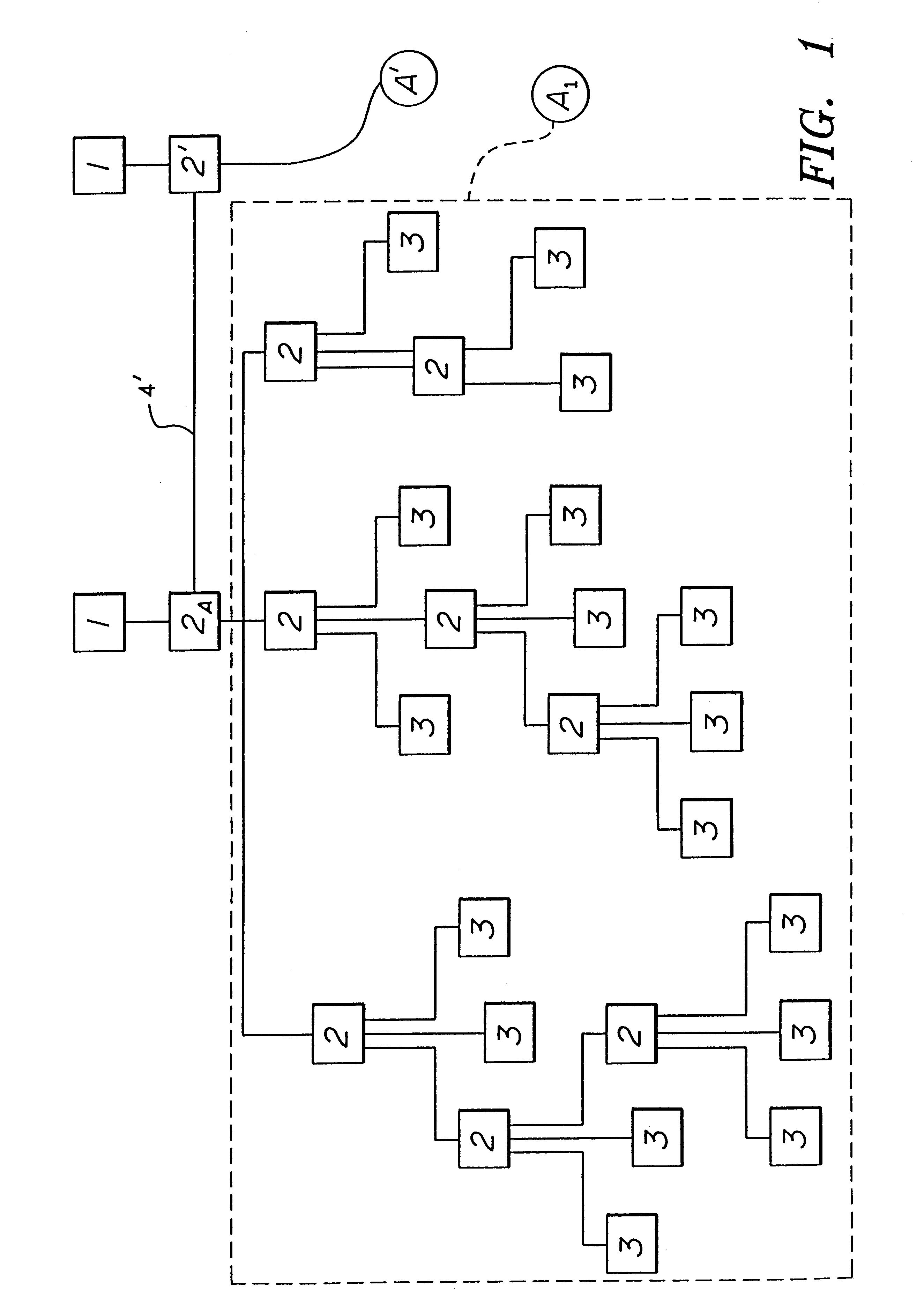
Referring to the drawings in general and to FIG. 1 in particular, there is depicted a power distribution system manifesting aspects of the invention where the power distribution system, which is not numbered, includes a plurality of power sources with each power source being designated generally 1. The power distribution system further includes a plurality of loads, each of which is designated generally 3, receiving power supplied by power sources 1 and performing various functions in accordance with the design of the power distribution system. The system further includes a plurality of integrated power node control centers, each of which has been designated generally 2. The system further includes a plurality of branches 4 for carrying electrical power supplied by sources 1 to loads 3. Branches 4 interconnect at control centers 2 as illustrated in FIG. 1.

Dotted rectangle A.sub.1 in FIG. 1 has been drawn to surround a plurality of the control centers 2, loads 3 and branches 4. Sever...


PUM


Abstract

An electrical integrated modular power node includes a power module having a common backplane with a plurality of bus bars for supplying the power requirements for the node, functional components and circuitry for connection through selected bus bars to a power supply for providing loads with power as required thereby with individual functional modules providing geometrical packages having bounding surfaces conforming to bounding surfaces of adjacent modules including the power module, for enclosing and supporting functional components and circuitry design so the conforming surfaces of the modules abut with one another in a position to be connected at abutting surfaces with at least some of the modules facing the power module to connect to connectors on the bus bars providing power as required by the load to which circuitry within the connected module is connected with the connectors mechanically supporting the modules relative to power module and to one another.

Description

FIELD AND BACKGROUND OF THE INVENTIONThis invention relates to power distribution systems and to methods and apparatus for controlling and protecting such power distribution systems, with emphasis on power distribution systems used in both military and commercial nautical applications and large land transportation vehicles.DESCRIPTION OF THE PRIOR ARTElectrical power distribution systems normally include power sources and many loads, with the loads connected to the sources by branches. Typically, those branches connect together at nodes. The nodes and branches may be provided in a hub and spoke configuration.Typically, nodes are custom-tailored to fit a particular need of the electrical power distribution system at a particular node location. Small nodes may handle small blocks of power. Large nodes may handle large blocks of power and include numerous functions performed at the node. One type of node is a power panel, which is typically a small node and in the prior art, incorporat...

Claims


Application Information

Patent Timeline
IPC IPC(8): H02H3/00H02J13/00
CPCH02J13/0086H02H3/00H02J13/00017H02J13/0004Y04S40/124Y02E60/00
Inventor YKEMA, JOHN I.
Owner L 3 COMM SPD TECH
Why Eureka
Try Eureka