

Dual mode tracking system
a dual-mode tracking and tracking system technology, applied in the field of rfid (radio frequency identification) systems, can solve the problems of more expensive active tags to be used in lower volume applications where continuous tracking is not feasible, and the passive systems can only be read at a limited number of fixed locations
- Summary
- Abstract
- Description
- Claims
- Application Information
AI Technical Summary
Problems solved by technology
Method used
Image

Examples
embodiment 400
The tag RF circuitry 300 shown in FIG. 3 is intended to illustrate the general functions of a tag 101a-c, with an embodiment that is workable and self-explanatory. Those skilled in the art will be able to combine multiple functions into single elements in order to conserve power and take full advantage of available parts, or implement the same functions with a custom ASIC. FIG. 4 shows an alternative embodiment 400 which fulfills the same basic functions as that shown in FIG. 3, but with fewer components and using less power. The essential difference between the circuitry 400 shown in FIG. 4 and the circuitry 300 shown in FIG. 3 is that the modulator 404 in FIG. 4 is placed before the frequency mixer 406 in order to reduce the number of components (for example, the amplifier 310 is eliminated) and to conserve power.
In the place of the frequency mixer 304 (FIG. 3) or the time delay element 1505 (FIG. 13), other signal transmission discriminators may be used to transpond by other meth...
embodiment 1500
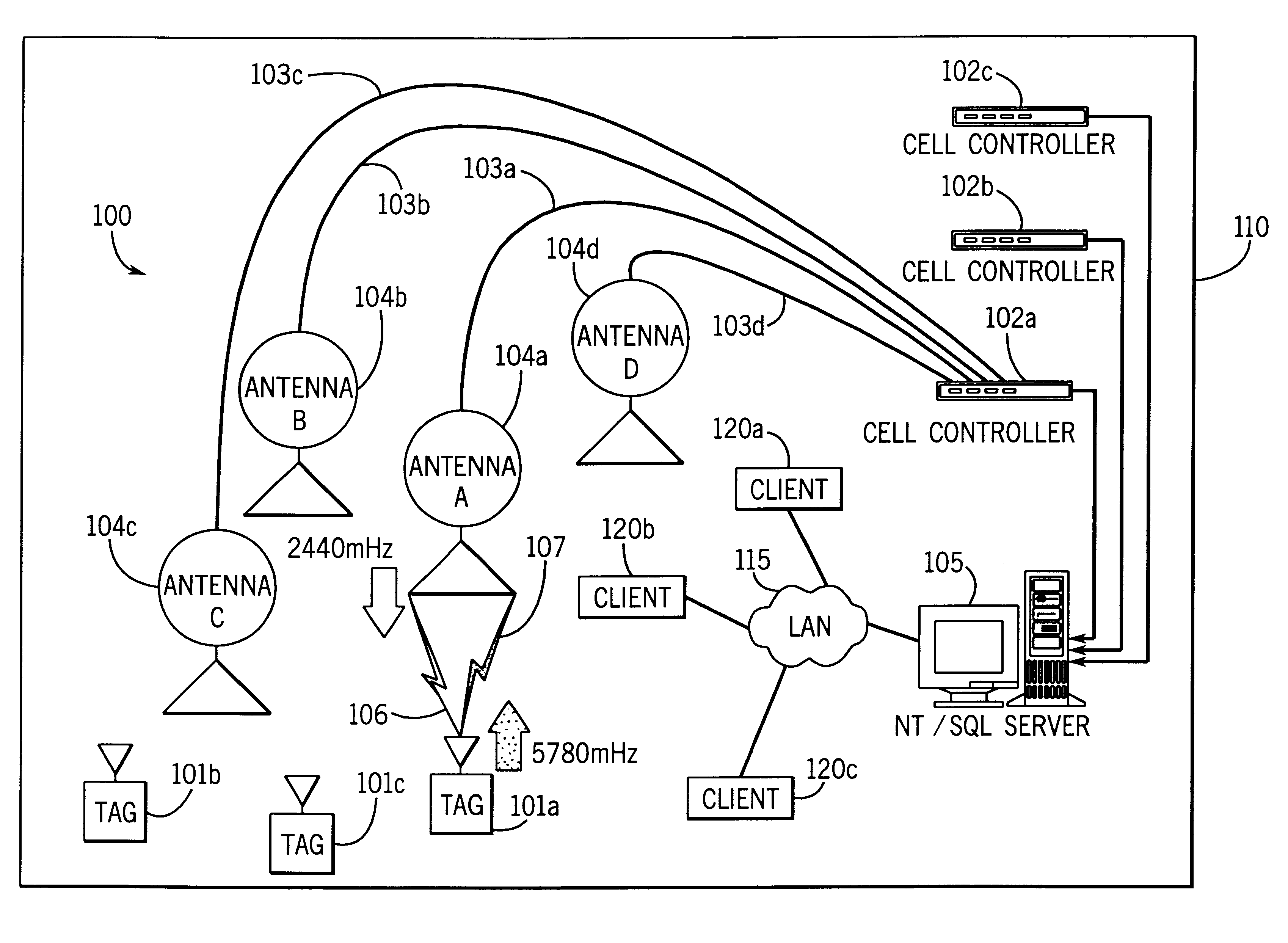
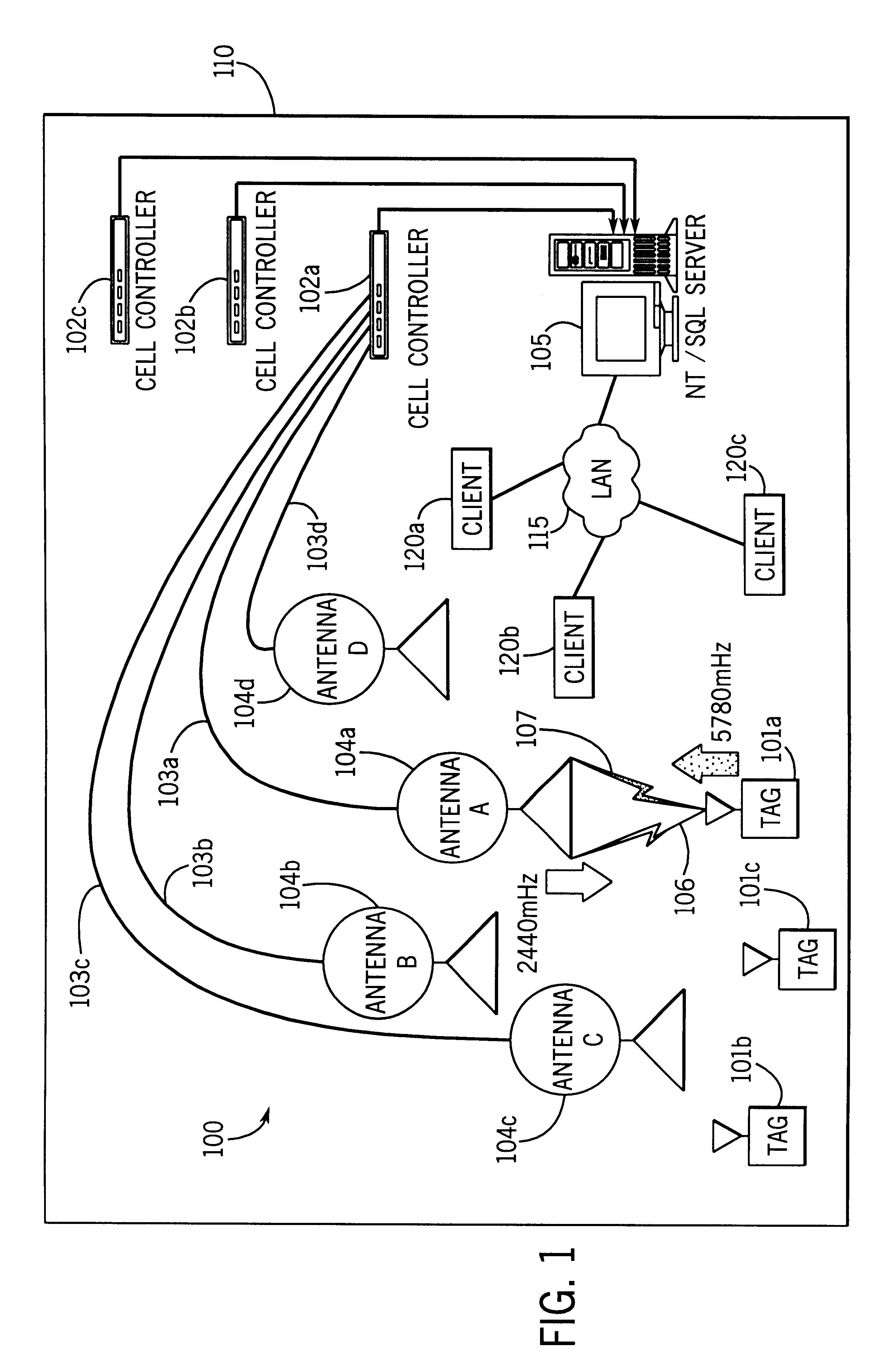
The tag RF circuitry 300, 400 shown in FIGS. 3 and 4 use frequency division multiple access, i.e., the tag circuitry 300, 400 receives and emits signals on different frequencies. An alternative embodiment 1500 uses time division multiple access, as shown in FIG. 13. For illustrative purposes, assume that the tag circuitry 1500 shown in FIG. 13 takes as an input at a receive antenna 1501 a signal at one frequency, such as 915 mHz, and emits the same signal through a transmit antenna 1508 at the same frequency after a delay of a microsecond. Assume that a cell controller, such as cell controller 102a, transmits an interrogation signal 106 in bursts every 2 microseconds. A tag, such as tag 101a, takes this signal as an input through the receive antenna 1501. The signal then passes through elements 1502-1504, as in FIGS. 3 and 4. A time delay element 1505 is then used to delay for a microsecond. The signal then passes through a transmit bandpass filter 1507 and is emitted from the trans...
PUM
 Abstract
Description
Claims
Application Information