
Method and device for continuous dyeing of warp ends

Inactive Publication Date: 2002-03-12
GULLSHIELD
View PDF9 Cites 25 Cited by
  • Summary
  • Abstract
  • Description
  • Claims
  • Application Information

AI Technical Summary

Benefits of technology

It is an object of the invention therefore to eliminate the disadvantages of conventional processes for the continuous dyeing of warp yarn, particularly cotton warp yarn, with indigo or other groups of dyestuffs when after impregnation and squeezing-off require oxidation or heat treatment for development and fixing. In particular, an object is to achieve a definite reduction in the amount of dyeing liquor required, and to create economically favorable prerequisites for cooling or heating the dyeing liquor. At the same time, an object is to make it possible for the residence time of the warp yarn band in the dyeing installation to be variable using simple structural means, and for the fixing temperature to be selectable from below room temperature to above 100.degree. C.
An object of the present invention is, therefore, to provide a process for the continuous dyeing of warp yarn, particularly cotton warp yarn, with indigo or other groups of dyestuffs, which makes a high degree of variability possible when dyeing warp yarns with different color shades, and with different groups of dyestuffs also, and to provide an apparatus which effects dyeing under the optimum conditions in each case when using indigo dye, or sulphide or vat dyes according to choice.
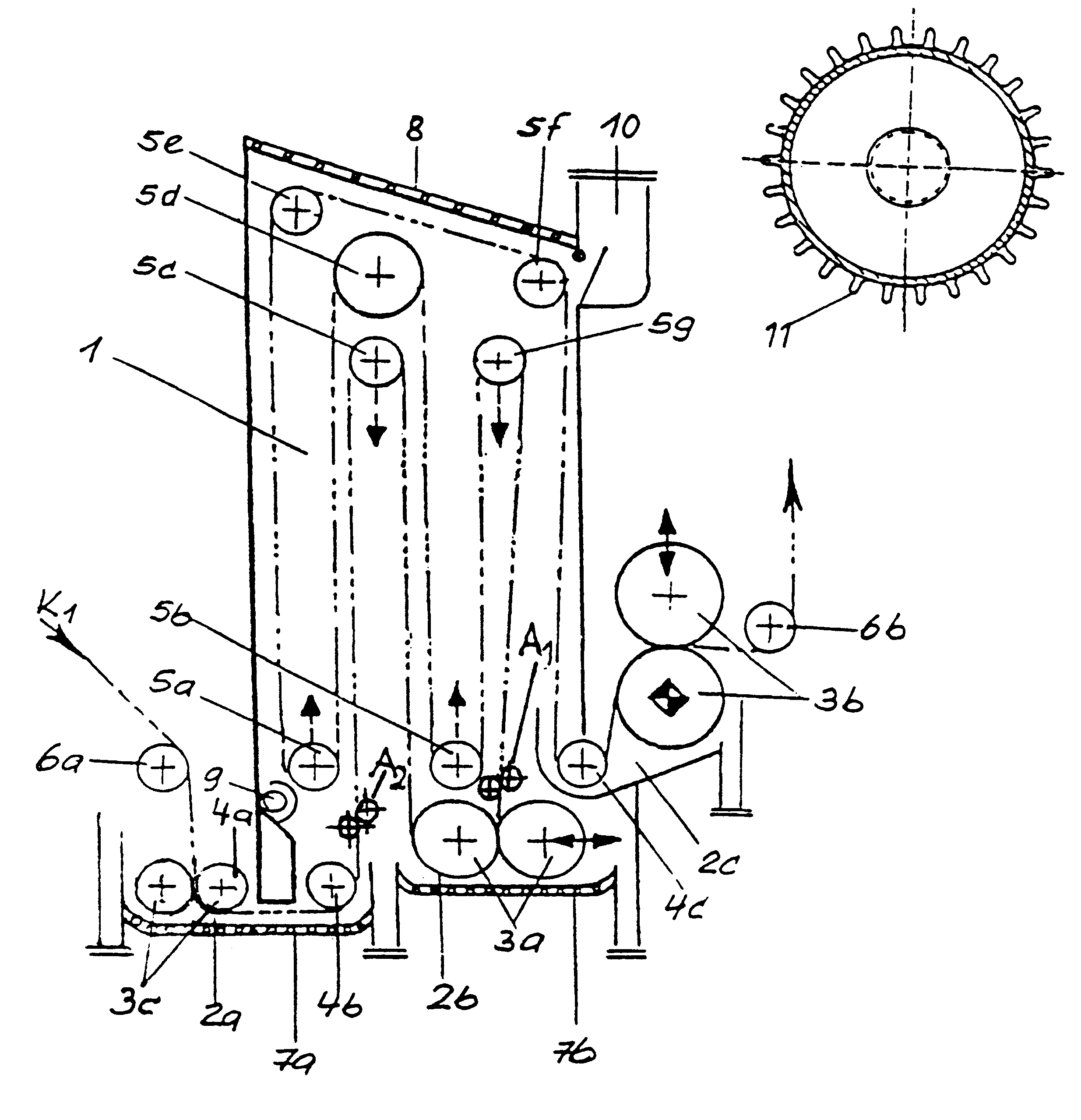
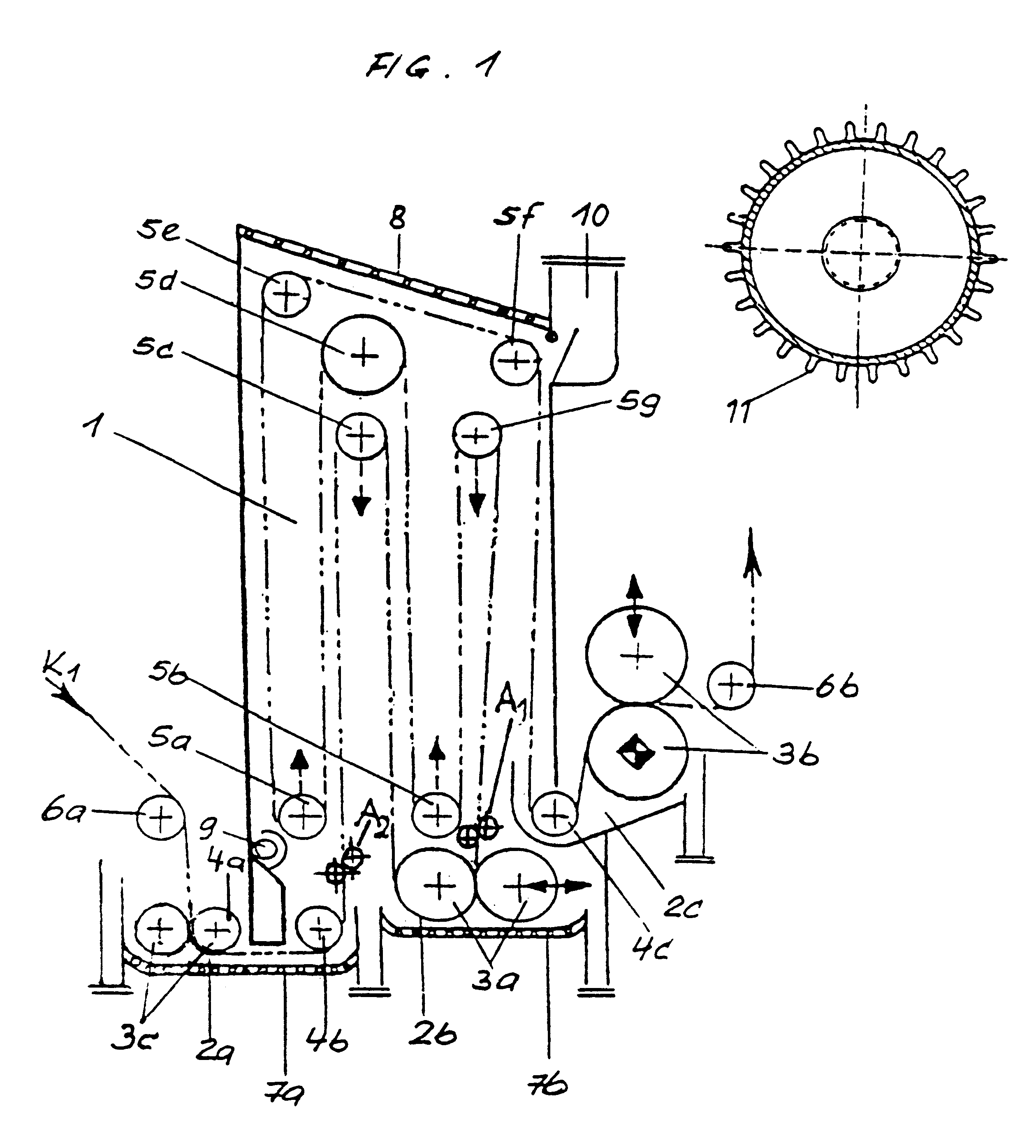
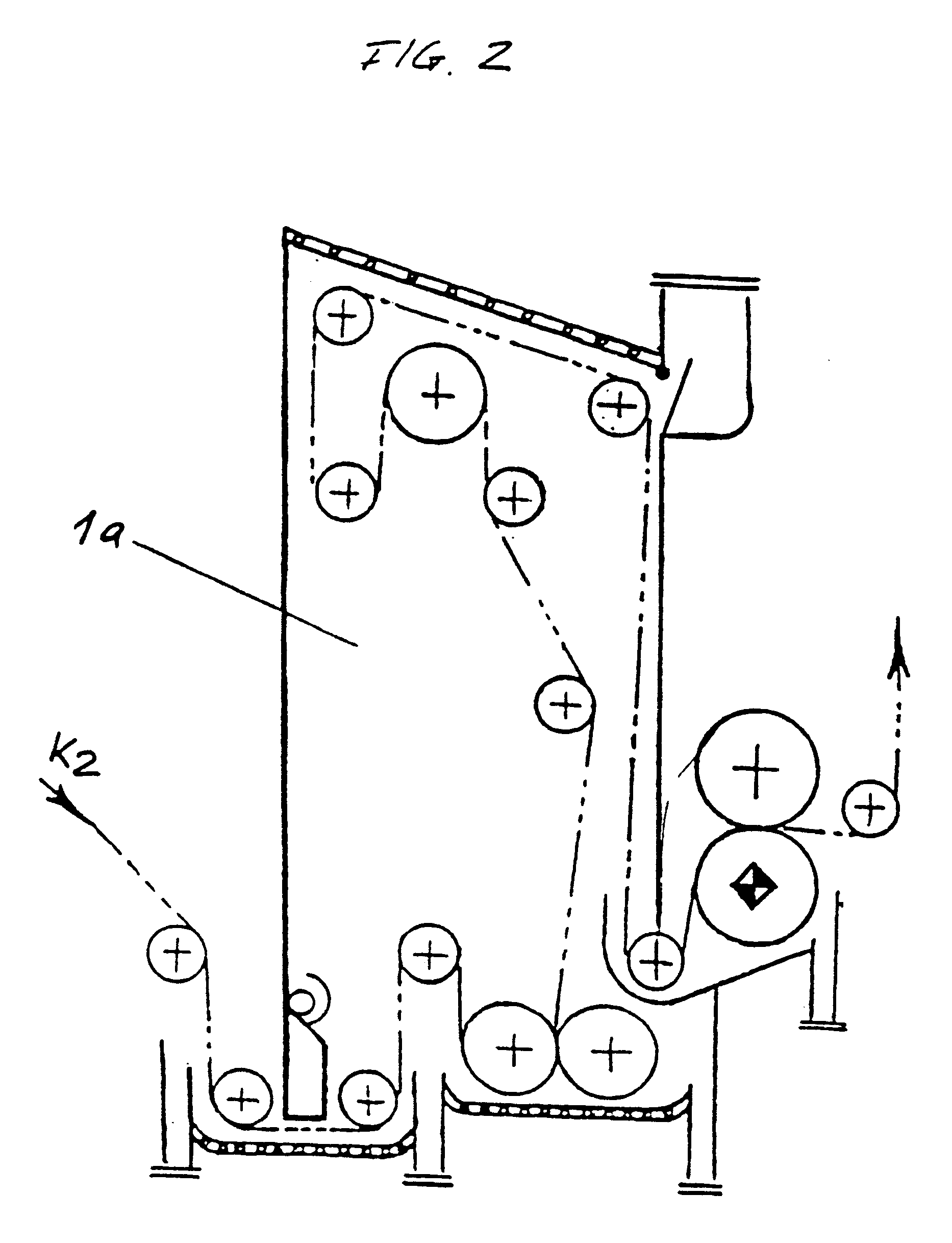
The dyeing reactor according to the invention is a vessel which is closed at the top and which has openings at its bottom end for the inlet and outlet of the warp yarn band. Vessels for the dyeing liquor, in which the bottom reactor opening is immersed, are disposed under the dyeing reactor. These vessels at the same time form a water lock with guide and deflection rollers which seal the dyeing reactor from the surroundings and by means of which the warp yarn band is fed in and discharged. In addition, a further squeezing device may be disposed in the inlet vat, which squeezes out air which is still contained in the entering warp yarn band. These vessels are equipped with double bottoms by means of which the indigo dyeing liquor can be cooled, or by means of which other dye baths, for example sulphide dyes, can be heated. An intermediate squeezing device is disposed in the dyeing reactor, the squeezing pressure of which can be adjusted in a variable manner down to zero pressure. Instead of the intermediate squeezing device, or in addition thereto, pairs of rollers can be used which strip off excess dyeing liquor when the squeezing device is opened and which thus prevent dyeing liquor from dripping off. The pairs of rollers are adjustable, and are disposed so that the warp yarn band has to follow a more or less pronounced S-shaped curve or a Z-shaped curve. The dwell time of the warp yarn band can be shortened or prolonged, depending on the technological requirements, by guide and deflection rollers which are disposed in the inside of the dyeing reactor and which are vertically displaceable in its interior space.

Problems solved by technology

These units therefore cannot be used for the main production operation of indigo dyeing.
This means that conventional indigo dyeing installations have to be reset for the production of different depths of shade.
This is economically disadvantageous, however due to the multiplicity of dyeing vessels and the large amount of dyeing liquor.
Another problem which occurs with the conventional dyeing machines is that the dyestuff is extracted from the dyeing bath due to its affinity.
This worrying phenomenon, which can manifest itself over several thousand meters of the warp to be dyed, occurs in particular in large installations which contain a large volume of dye bath, and which result in long dyeing runs.

Method used


Image

  • Method and device for continuous dyeing of warp ends
  • Method and device for continuous dyeing of warp ends
  • Method and device for continuous dyeing of warp ends

Examples


example 2

For dyeing black denim or colored denim with a sulphide dye, the procedure is the same in principle as that described in Example 1, except that only the first dyeing vessel 2a is employed here, and the total volume is thus reduced to 150+60+30=240 l.

Moreover, the dyeing liquor is heated to at least 90.degree. C. and the interior space of the reactor is heated by steam to 100.degree.-102.degree. C.

The warp thread intake is advantageously 16 m, since the long dwell time ensures the best dyestuff utilization.


PUM


Abstract

The invention relates to a method for the continuous dyeing of warp ends, in particular cotton warp ends, with indigo or other dyestuff groups which, after impregnating and squeezing out, require oxidation or thermal treatment for fixing. The method eliminates the disadvantages of traditional methods for the continuous dyeing of warp ends. In particular, the required bath amount is considerably reduced by this method. By using a new dyeing reactor (1), the residence time of the warp ends in the dyeing installation can be varied without having to increase the bath volume. The option of heating or cooling the dyeing bath enables a fixing temperature between below room temperature and over 100° C. to be chosen. Optimal conditions can thus be created for all dyeing methods which are habitual for warp ends. In this way, the number of immersion-oxidation processes in the indigo dyehouse can be reduced and the growing demand for indigo blue jeans material with different wash resistances and shades can thus be catered for with increased flexibility. And the same can be done for black and colored denim.

Description

This application is a national stage of PCT / IB97 / 01191 filed Oct. 20, 1997 and based upon EP 97 / 05573.6 filed Apr. 4, 1997 under the International Convention.This invention relates to a process for the continuous dyeing of warp yarn, particularly cotton warp yarn, with indigo or with other groups of dyestuffs, which after impregnation and squeezing-off, require oxidation or heat treatment for development and fixation.Continuous warp dying machines for the indigo dyeing of blue denim are known, which consist of connected dyeing vessels disposed in series and comprising a squeezing device, or of padding mangles with a relatively large bath volume. These dyeing vessels or padding mangles are also used for the dyeing of black and colored denim with sulfide or vat dyes. In order to solve color-running problems and in order to achieve an improved dyestuff utilization, it is known that additional units, which consist of a padding mangle with an economizer vat and a subsequent steamer, can ...

Claims


Application Information

Patent Timeline
IPC IPC(8): D06B23/16D06B3/10D06B23/00D06B3/00D06B3/18D06B17/00D06B19/00D06B21/00D06B21/02
CPCD06B3/10D06B3/18D06B23/16D06B19/0035D06B21/00D06B17/00
Inventor GODAU, ECKHARDT
Owner GULLSHIELD
Learn More