Power output unit, method of controlling the power output unit, and hybrid vehicle

a technology of power output unit and power output unit, which is applied in the direction of electric generator control, machine/engine control, process and machine control, etc., can solve the problems of increasing the design restrictions of the vehicle, the speed of the vehicle cannot be further increased, and the space occupation of the motor-generator

Inactive Publication Date: 2002-03-12
TOYOTA JIDOSHA KK
View PDF10 Cites 97 Cited by
  • Summary
  • Abstract
  • Description
  • Claims
  • Application Information

AI Technical Summary

Problems solved by technology

Therefore, even in the case where the engine 150 still outputs sufficient power in comparison with the aforementioned power requirement, the vehicle speed cannot further be increased.
However, if motor-generators larger in size are installed, the motor-generators occupy a greater space.
Therefore, there is caused a problem of an increase in restrictions imposed on the design of the vehicle.
Also, an increase in vehicle weight leads to a problem of deterioration of fuel consumption rate.

Method used


Image

  • Power output unit, method of controlling the power output unit, and hybrid vehicle
  • Power output unit, method of controlling the power output unit, and hybrid vehicle
  • Power output unit, method of controlling the power output unit, and hybrid vehicle

Examples


first embodiment

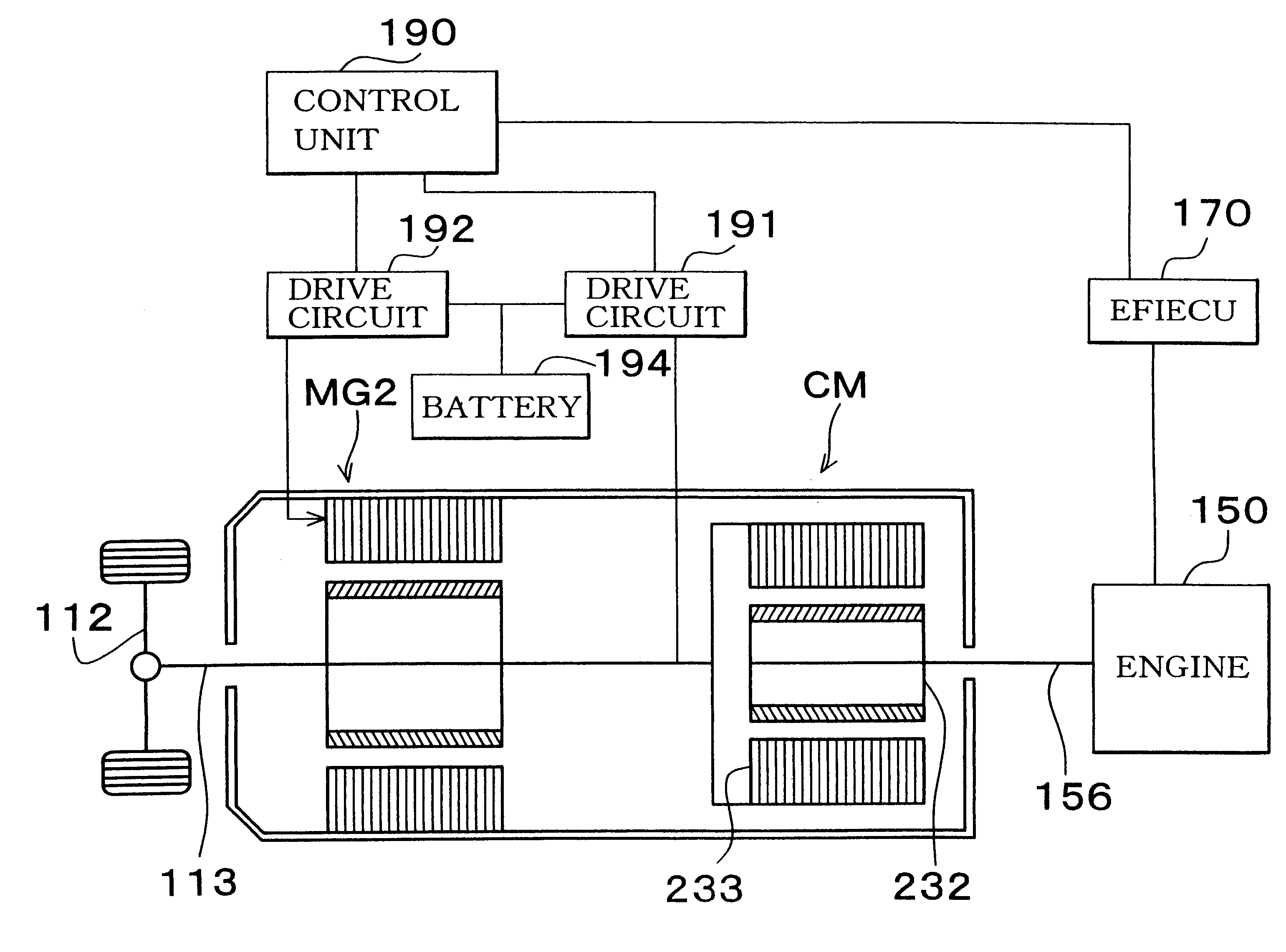
In the clutch motor CM, magnetic coupling between the inner rotor 232 and the outer rotor 233 can be controlled by controlling supply of electric current to the coil in the drive circuit 191. As in the first embodiment, the drive circuit 191 is composed of a transistor inverter. Through such magnetic coupling, a power that has been outputted from the engine 150 can be transmitted to the drive shaft 113. The inner rotor 232 and the outer rotor 233 are caused to rotate relative to each other with a predetermined amount of slippage, whereby an electric power corresponding to the amount of slippage can be regenerated. As a matter of course, it is possible to output a torque through the supply of electric power from the battery 194. Though composed of a single body, the clutch motor CM can achieve substantially the same effect as a combination of the planetary gear 120 and the motor MG1.

Also in such a hybrid vehicle, substantially the same control as in the first embodiment can be perfor...

second embodiment

In the hybrid vehicle of the second embodiment, the output torque of the clutch motor CM is equal to the output torque of the engine 150. Thus, if the target torque Tc* of the clutch motor CM is set, the target torque Te* of the engine 150 is also determined. Further, since the power requirement Pe* for the engine 150 has been calculated (STEP S120), the target rotational speed Ne* of the engine 150 is also determined based on the power requirement Pe* and the target torque Te*.

If it is determined that the operation state of the motor MG2 has not exceeded the threshold value, the power requirement Pe* for the engine is outputted. Therefore, an operation point of the highest efficiency is set for the engine 150. After such determination of the target torque Te* and the target rotational speed Ne* of the engine 150, the target torque Tc* of the clutch motor CM is set to a value equal to the target torque Te*. Based on a difference between the drive force Tp* and the target torque Tc* ...


PUM


Abstract

A power output unit of the present invention sufficiently ensures the performance of a vehicle by sufficiently developing the performance of an engine without enlarging a motor. In a hybrid vehicle, a power requirement for the engine is set based on a vehicle speed and an accelerator opening degree. Usually, while giving priority to efficiency, an operation state of the engine is set based on a power requirement. Once the operation state of the engine is set, operation states of first and second motors are set based on a vehicle speed and a drive force. If the thus-set operation state of the first or second motor exceeds a threshold value, the operation state of the first or second motor is set so as not to exceed the threshold value. Based on the setting result and the power requirement, an operation state of the engine is set.

Description

INCORPORATION BY REFERENCEThe disclosure of Japanese Patent Application No. HEI 11-136549 filed on May 18, 1999 including the specification, drawings and abstract is incorporated herein by reference in its entirety.1. Field of the InventionThe present invention relates to a power output unit, a method of controlling the power output unit, and a hybrid vehicle. More particularly, the present invention relates to a power output unit which has an internal combustion engine and motor-generators and in which an output shaft of the internal combustion engine, rotational shafts of the motor-generators and a drive shaft are mechanically connected to one another, a method of controlling the power output unit, and a hybrid vehicle.2. Description of the Related ArtIn recent years, various constructions have been proposed for a hybrid vehicle having motor-generators in addition to an internal combustion engine. A hybrid vehicle makes it possible to significantly reduce an amount of consumption ...

Claims


Application Information

Patent Timeline
Patent Type & Authority Patents(United States)
IPC IPC(8): B60K6/00B60L11/12B60K6/04B60L11/02B60K1/00B60K1/02B60K17/04B60K6/20B60K6/365B60K6/445B60K6/448B60L50/15B60L50/16B60W10/06B60W10/08B60W10/26B60W20/00F02D29/02H02P5/74
CPCB60K6/445B60K6/448B60L11/12B60W10/06B60W10/08B60W10/26B60W20/00B60K6/365B60K1/02Y02T10/6239B60L2240/421B60L2240/423B60W2510/081B60W2710/083Y02T10/56Y02T10/6243Y02T10/6286Y02T10/646Y02T10/7077Y10S903/903Y10S903/91Y02T10/648B60L50/15Y02T10/40Y02T10/62Y02T10/64Y02T10/7072B60W20/10
Inventor ABE, TETSUYA
Owner TOYOTA JIDOSHA KK
Why Eureka
Try Eureka