Hybrid electric tool carrier

a hybrid electric vehicle and tool carrier technology, applied in the field of utility vehicles, can solve the problems of affecting tire scuffing, and limited ability to trim on either side of the machine, and achieve the effects of improving the placement of vehicle components, improving the steering arrangement, and improving the driving arrangemen

Active Publication Date: 2006-03-28
DEERE & CO
View PDF14 Cites 148 Cited by
  • Summary
  • Abstract
  • Description
  • Claims
  • Application Information

AI Technical Summary

Benefits of technology

[0011]It is yet another object of the present invention to provide an improved hybrid utility vehicle. It is a further object to provide such a vehicle which facilitates better placement of vehicle components and attachments.
[0012]It is another object to provide an improved hybrid utility vehicle having improved power distribution structure.
[0013]In one embodiment of the invention, a hybrid utility vehicle includes a tool-supporting frame and an electrical power source driven by an engine. Right and left rear wheels independently driven by permanent magnet electric motors and front wheels electrically steerable over a range of approximately 180 degrees operate under the control of a vehicle controller responsive to steering and speed input controls to provide zero turn radius operation with minimum slippage and tire scuffing at varying vehicle speeds. Space efficiency provided by the electric steering and an electrically driven tool deck facilitate a variety of tool mounting configurations including a rear discharge deck with a chute passing under the vehicle frame between the driven wheels. The electric wheel motor drives are on the external side of the frame rails, and the cut material conveying chute may be mounted much lower than is possible in a traditional lawn tractor layout which requires chute routing over a transmission. The hybrid construction eliminates need for a traditional transmission so the space can be used for moving grass and other cut material to a rear hopper. Also, the material chute located in the middle rather than at a side of the machine facilitates trimming unhindered by discharge structure on either side of the machine.
[0014]An inverter connected to the electrical power source provides 110 and / or 220 volt output for utility power use so hand tools and lawn tools can be operated and back-up house power can be provided from the vehicle. The power source also functions as a high powered, high rpm, low noise starter motor. The controller filters operator speed requests utilizing a torque control map. A control algorithm avoids engine overload and engine stoppage by causing electrical load to be taken from the battery pack and gradually applying generator load to allow governor to match engine droop.

Problems solved by technology

Usually the cut material discharge chute is located on the side of the deck, and therefore the ability to trim on either side of the machine is limited.
However, when making tight turns, such as when mowing around a tree, wheel slip will cause tire scuffing and will tear up turf.
Zero turn radius vehicles are sometimes uncomfortable for some first time users to operate, and operation on slopes can be difficult with the front caster wheel construction.
Commonly assigned U.S. Pat. No. 6,454,032 shows a drive and steer type of arrangement providing automotive type of controls which are more comfortable to most consumers, but positive front wheel steer for better control on slopes is lacking.
With permanent magnet generators, the option to vary field current and thus the magnetic flux to vary output voltage is unavailable.
Driving the generator at different speeds causes considerable variation in the output voltage.
To provide sufficient operating voltage, the generator must either be wound for sufficient voltage at low engine speed which results in high over-voltage at full engine speed, or be wound for high speeds which requires constant full engine speed operation even if power requirements are low.
Typical ring gear starter configurations for hybrid vehicles are noisy, and cranking speed is relatively slow.
The starter motor adds cost and weight to the vehicle.
Engine overload and engine stoppage, particularly upon initial loading of the electrical system, can be a problem.

Method used


Image

  • Hybrid electric tool carrier
  • Hybrid electric tool carrier
  • Hybrid electric tool carrier

Examples


Embodiment Construction

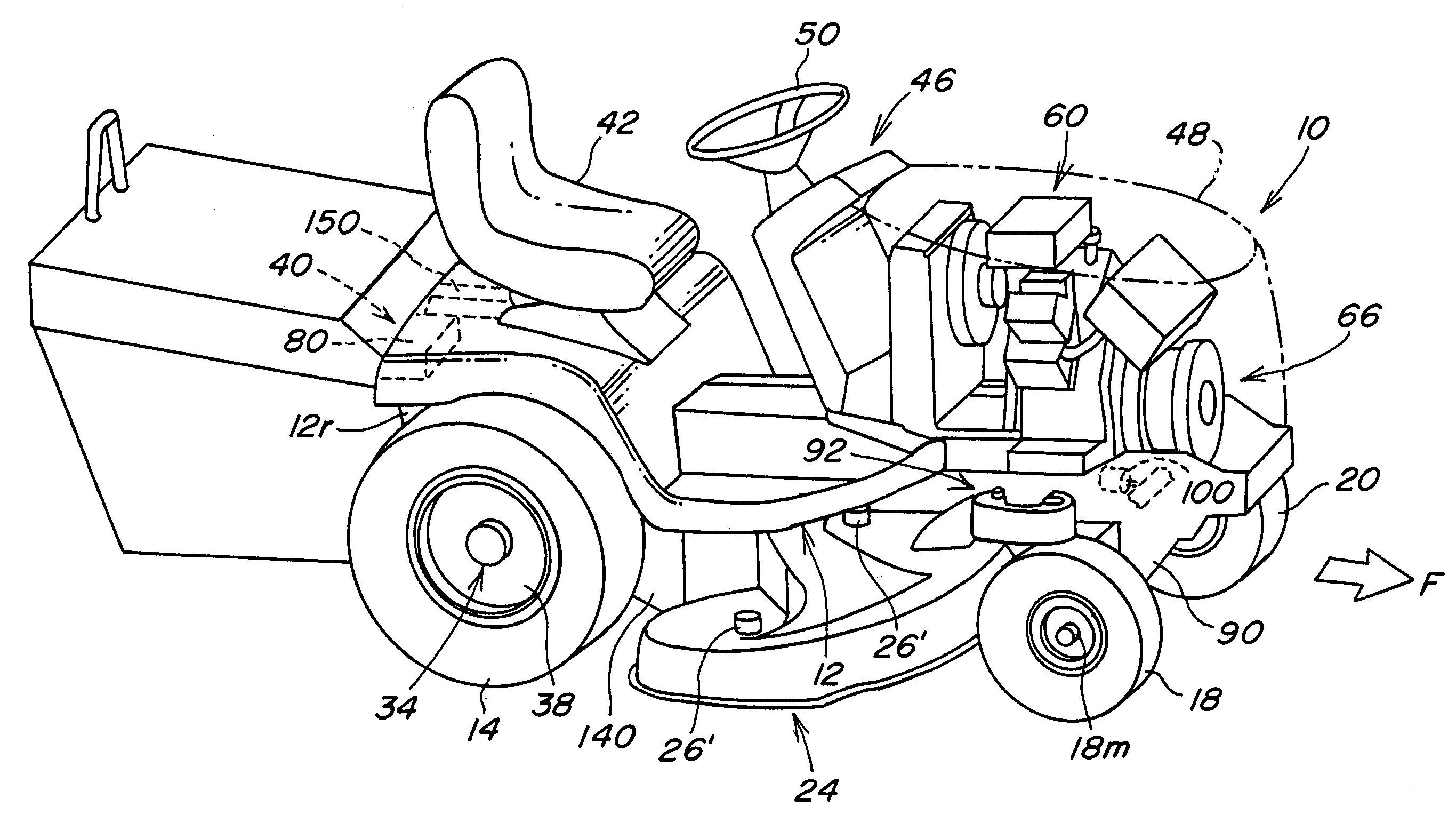
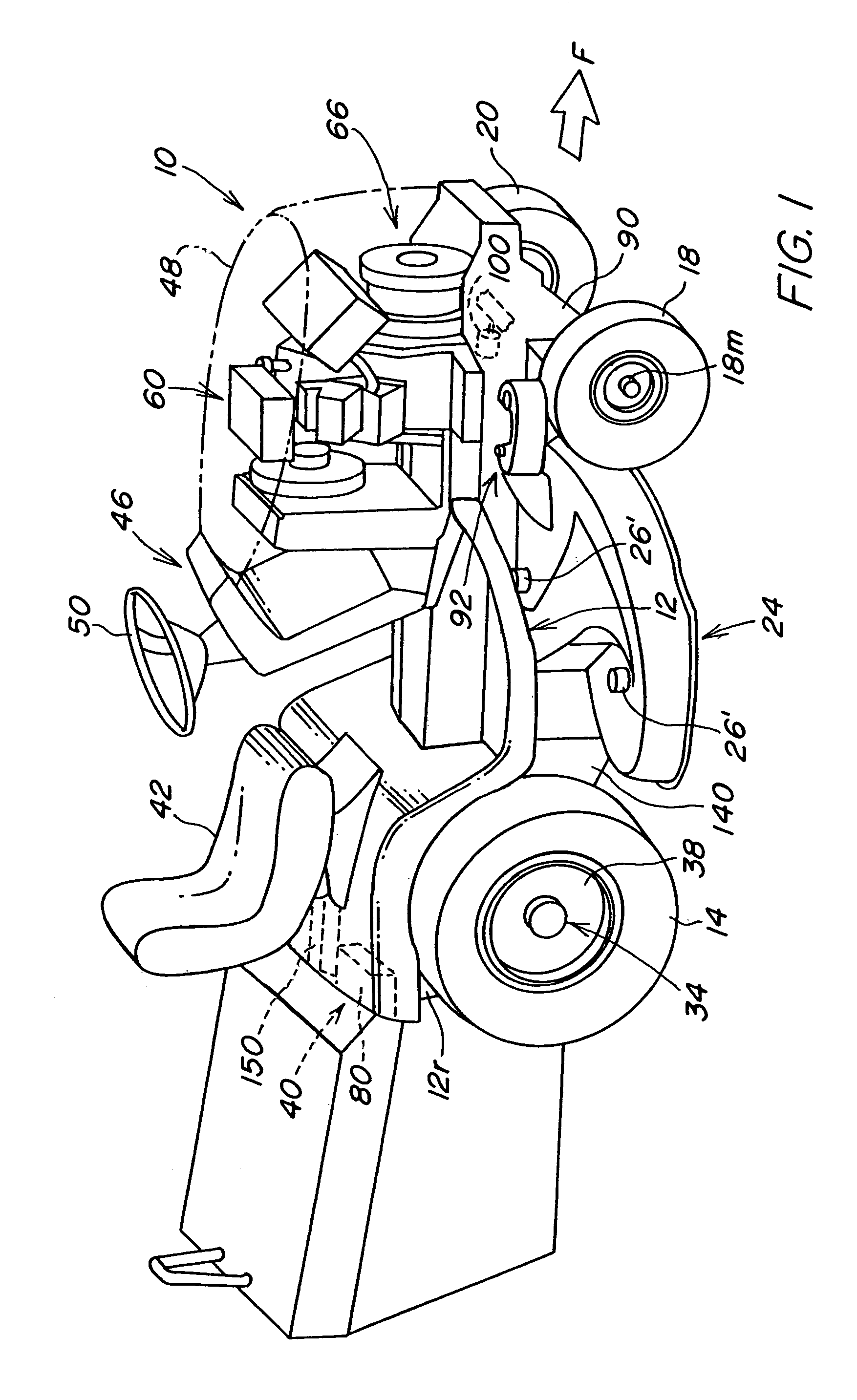
[0022]Referring now to FIG. 1, therein is shown a utility vehicle 10 such as a riding mower or other grounds care machine having a tool-carrying frame 12 supported by right and left rear driven wheels 14 and 16 and front steerable wheels 18 and 20. A driven tool 24, shown in FIG. 1 as a mower deck, is supported from the underside of the frame 12 and includes a plurality of driven blade members 26 (FIG. 3) powered by electric motor structure 26′. The electric motor structure 26′ may include a permanent magnet dc motors 26′ individually driving each of the blade members 26 or other suitable drive arrangement including but not limited to a single motor driving the blade members 26 through a belt drive. The motors 26′ can be “pancake” type motors to for more clearance on the top of the deck 24.

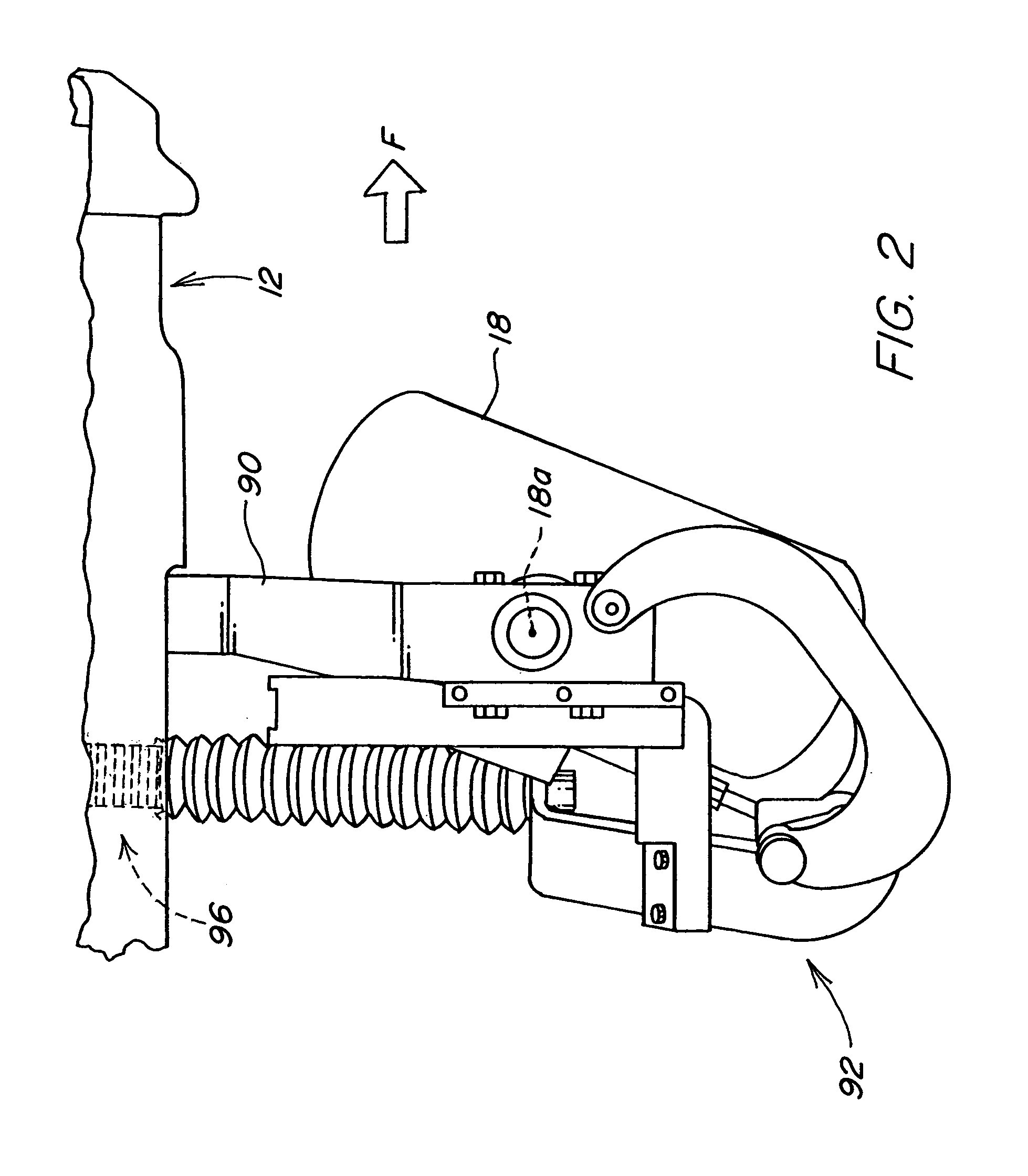
[0023]The frame 12 includes a rear frame portion 12r on each side of the vehicle 10 supporting right and left integrated wheel motor assemblies 34 and 36, each having a brushless permanent magnet ...


PUM


Abstract

A hybrid utility vehicle includes a tool-supporting frame and an electrical power source driven by an engine. Right and left rear wheels independently driven by permanent magnet electric motors and front wheels electrically steerable over a range of approximately 180 degrees operate under the control of a vehicle controller responsive to steering and speed input controls to provide zero turn radius operation with minimum slippage and tire scuffing. Space efficiency provided by the electric steering and an electrically driven tool deck facilitate a variety of tool mounting configurations including a rear discharge deck with a chute passing under the vehicle frame between the driven wheels. An inverter connected to the electrical power source provides 110 / 220 volt output. The power source also functions as a high powered, high rpm, low noise starter motor.

Description

FIELD OF THE INVENTION[0001]The present invention relates generally to utility vehicles and more specifically to off-road hybrid electric vehicles such as lawn and garden tractors.BACKGROUND OF THE INVENTION[0002]Off-road utility vehicles such as garden tractors typically include a basic carrier unit with an internal combustion engine and electrical power source. The carrier unit is powered by the engine, either through a direct mechanical drive or a hydraulic drive, or indirectly through the electrical power supply and one or more electric traction motors.[0003]The carrier unit accepts various selectively replaceable attachments which are powered by the engine and / or electrical source. For example, a riding lawn mower includes a deck supported under a vehicle frame. Usually the cut material discharge chute is located on the side of the deck, and therefore the ability to trim on either side of the machine is limited. Some rear discharge machines have chutes which pass over a rear fr...

Claims


Application Information

Patent Timeline
Patent Type & Authority Patents(United States)
IPC IPC(8): A01D34/03A01D34/43A01D34/64B60K6/46B60K7/00B60W10/08B62D11/00B62D11/04B62D11/24
CPCB60W10/08B62D11/003B62D11/04B60K6/46B60K7/0007B62D11/24B60Y2200/223B60K17/046Y02T10/6217Y02T10/62B60W2540/18A01D69/025A01D34/64
Inventor HUNT, KENNETH EDWARDSHOEMAKER, JIM MILTONFERREE, PHILIP EUGENE
Owner DEERE & CO
Why Eureka
Try Eureka