
Driver Feedback to Improve Vehicle Performance

a technology of driver feedback and vehicle performance, applied in the direction of electric propulsion mounting, braking system, transportation and packaging, etc., can solve the problems of reducing the potential fuel economy gains achieved through regenerative braking, activating dissipative braking, and operating vehicles typically achieve less fuel economy performance of hybrid vehicles, so as to improve overall fuel economy

Active Publication Date: 2008-02-21
FORD GLOBAL TECH LLC
View PDF9 Cites 138 Cited by
  • Summary
  • Abstract
  • Description
  • Claims
  • Application Information

AI Technical Summary

Benefits of technology

[0001]Various operations and strategies may be used in hybrid vehicles to improve overall fuel economy. One approach utilizes regenerative braking where vehicle braking energy is stored for later use in propelling the vehicle. For example, in hybrid-electric vehicles, an electric machine may be at least partially coupled to the wheels / powertrain to provide braking torque by generating electrical energy that may be stored in a battery or other electric storage device. Thus, during later propulsion, the stored electrical energy may be converted to propel the vehicle, thereby saving fuel that would otherwise be spent in the engine, for example.
[0002]Because such regenerative braking systems may not generally provide sufficient braking performance for all vehicle operating conditions, hybrid vehicles may additionally utilize dissipative brake systems to brake the vehicle. For example, if a driver requests more braking than can be provided by the regenerative brake system, mechanical-friction wheel brakes may be applied on one or more wheels. In this way, sufficient vehicle braking performance can be provided.
[0003]However, the inventor herein has recognized a problem with such systems in practice especially when a particular class of drivers operate the vehicle. Specifically, some vehicle operators aggressively actuate the drive controls, such as the gas pedal and / or brake pedal, even when aggressive pedal or brake actuation may not be required. As a result, these operators typically achieve less fuel economy performance from hybrid vehicles because the aggressive brake actuation, for example, results in more dissipative braking than necessary, thus reducing the potential fuel economy gains achievable through regenerative braking.
[0005]In this way, it may be possible to give feedback to the operator that indicates when driver braking actuation surpasses that which can be provided by the regenerative braking system, thus causing activation of dissipative braking. As such, the operator can learn by experience and real-time feedback how to apply less brake actuation for various conditions when possible to improve use of regenerative braking and thus improve vehicle fuel economy. In other words, the operator can learn at what point of brake actuation dissipative braking is applied for a given set of conditions, and can then adjust brake actuation, when possible to reduce use of the dissipative braking.

Problems solved by technology

Because such regenerative braking systems may not generally provide sufficient braking performance for all vehicle operating conditions, hybrid vehicles may additionally utilize dissipative brake systems to brake the vehicle.
However, the inventor herein has recognized a problem with such systems in practice especially when a particular class of drivers operate the vehicle.
As a result, these operators typically achieve less fuel economy performance from hybrid vehicles because the aggressive brake actuation, for example, results in more dissipative braking than necessary, thus reducing the potential fuel economy gains achievable through regenerative braking.
In this way, it may be possible to give feedback to the operator that indicates when driver braking actuation surpasses that which can be provided by the regenerative braking system, thus causing activation of dissipative braking.

Method used


Image

  • Driver Feedback to Improve Vehicle Performance
  • Driver Feedback to Improve Vehicle Performance
  • Driver Feedback to Improve Vehicle Performance

Examples


Embodiment Construction

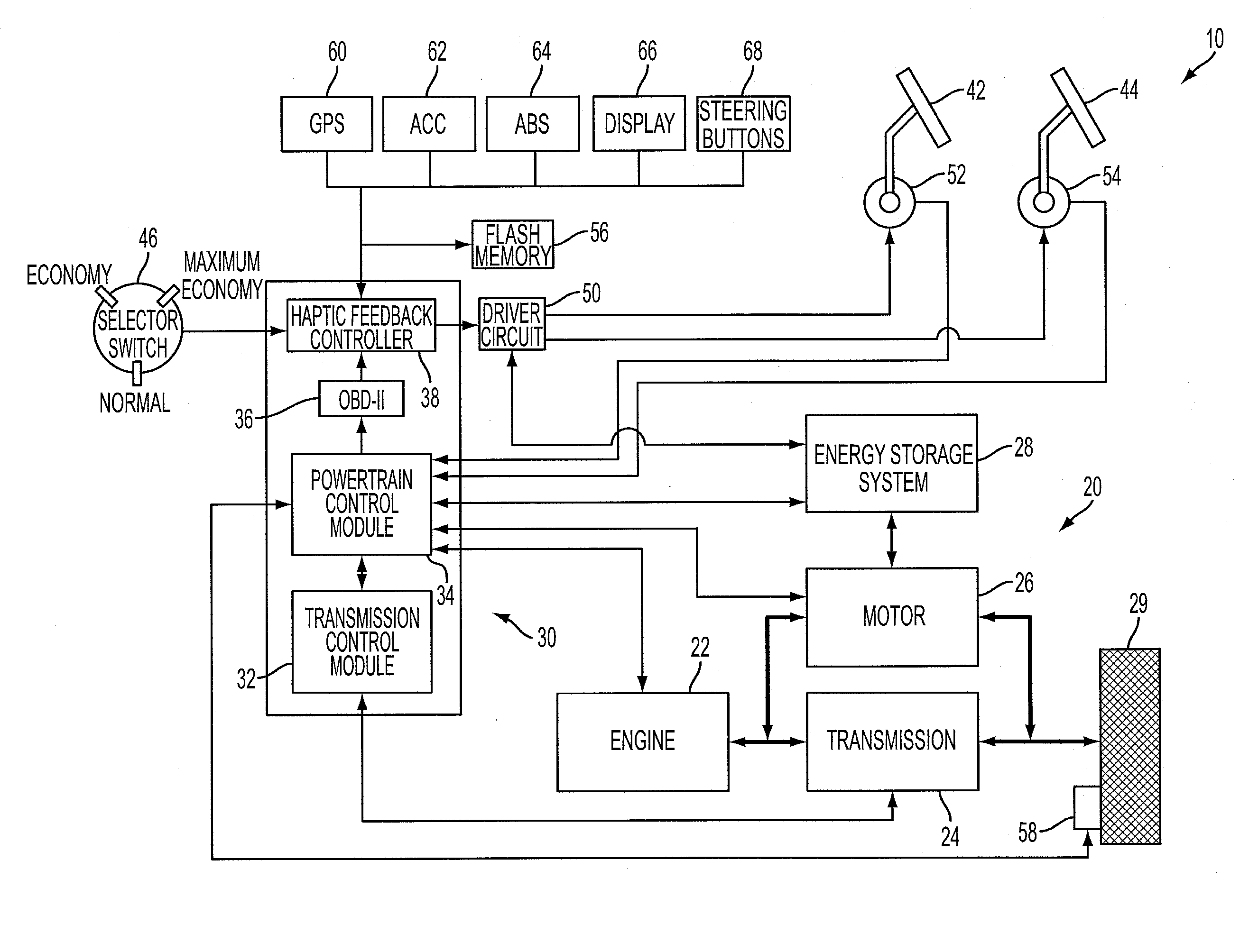
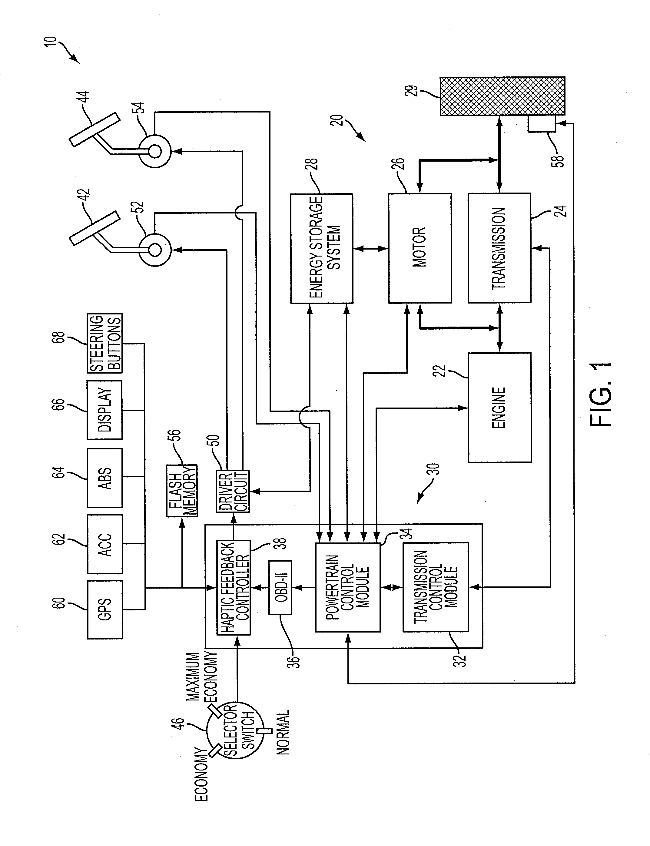
[0010]Referring to FIG. 1, a block diagram of a vehicle system 10 is shown. Vehicle system 10 may include a propulsion system 20 including an internal combustion engine 22 that may be used to supply torque to at least one drive wheel 29 via a transmission 24. Vehicle system 10 may also include a motor 26 that may be used to supply torque to the engine and / or drive wheels of the vehicles during some operations in what may be referred to as a hybrid vehicle. Motor 26 may also be operated to selectively absorb torque from the engine and / or drive wheels by performing a generator function. Torque absorbed by motor 26 may be converted to an energy form suitable for storage in an energy storage system 28. As one example, motor 26 may include an electric motor and energy storage system 28 may include one or more batteries for storing electrical energy. As another example, motor 26 may include a hydraulic motor and energy storage system 28 may include one or more vessels suitable for storing...


PUM


Abstract

A system for a hybrid vehicle driver by an operator, comprising of an energy storage device, a regenerative braking system coupled to the energy storage device, a dissipative braking system coupled to the vehicle, a brake lever, a haptic operator interface, and a control system for operating one or both of the regenerative and dissipative braking system in response to actuation of the brake lever, and providing feedback to the operator through the haptic interface differentiating a type of braking operation.

Description

BACKGROUND AND SUMMARY[0001]Various operations and strategies may be used in hybrid vehicles to improve overall fuel economy. One approach utilizes regenerative braking where vehicle braking energy is stored for later use in propelling the vehicle. For example, in hybrid-electric vehicles, an electric machine may be at least partially coupled to the wheels / powertrain to provide braking torque by generating electrical energy that may be stored in a battery or other electric storage device. Thus, during later propulsion, the stored electrical energy may be converted to propel the vehicle, thereby saving fuel that would otherwise be spent in the engine, for example.[0002]Because such regenerative braking systems may not generally provide sufficient braking performance for all vehicle operating conditions, hybrid vehicles may additionally utilize dissipative brake systems to brake the vehicle. For example, if a driver requests more braking than can be provided by the regenerative brake ...

Claims


Application Information

Patent Timeline
Patent Type & Authority Applications(United States)
IPC IPC(8): B60T8/64
CPCB60K6/48B60T1/10B60W10/08B60W10/184Y02T10/6221B60W30/18127B60W50/16B60W2510/244B60W2550/142B60W20/00B60W2050/143B60W2540/12B60W2552/15Y02T10/62B60W10/04B60W2540/215
Inventor LEWIS, DONALD J.RUSSELL, JOHN D.TUTTLE, CHRISTOPHER S.
Owner FORD GLOBAL TECH LLC
Learn More