Method of determining cable impedance

a cable impedance and cable technology, applied in the field of cable impedance determination, can solve the problems of cable inductance change, limited inductance and resistance of actual welding operation, and inability to obtain actual inductance and resistance of welding operation, etc., and achieve the effect of accurate determination of network inductan

Inactive Publication Date: 2002-03-19
LINCOLN GLOBAL INC
View PDF1 Cites 97 Cited by
  • Summary
  • Abstract
  • Description
  • Claims
  • Application Information

AI Technical Summary

Benefits of technology

Still a further object of the present invention is the provision of a method, as defined above, which method provides an accurate determination of the network inductance without requiring the concept of increasing voltage and periodically reading the current to measure di/dt.
Yet anothe

Problems solved by technology

Welding processes are generally intolerant to poor circuit conditions that cause changes in the inductance of the cables.
However, such leads have certain limitations.
The use of these leads can identify certain problems; however, the actual inductance and resistance of the welding operation is not obtained.
These systems have become necessary as welding control technology has advanced and become quite complex.
However, these two stages are done

Method used


Image

  • Method of determining cable impedance
  • Method of determining cable impedance
  • Method of determining cable impedance

Examples


Embodiment Construction

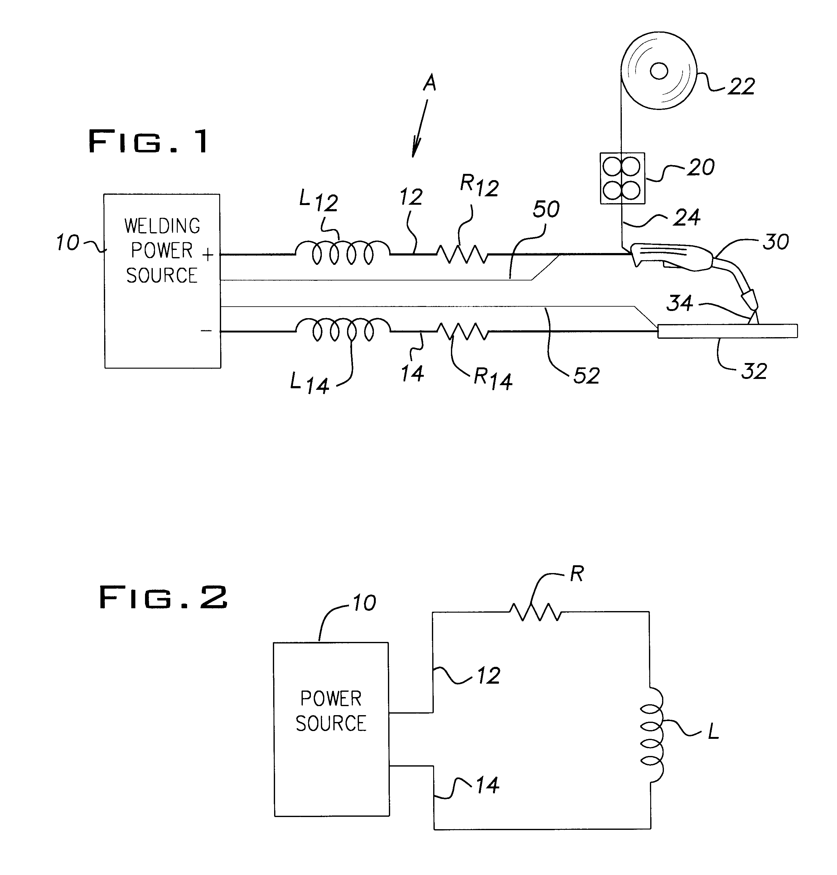
Referring now to the drawings wherein the showings are for the purpose of illustrating the preferred embodiment of the invention only, and not for the purpose of limiting same, FIG. 1 schematically represents an arc welding installation A including a power supply 10 with two welding cables 12, 14 forming the connecting network between the power supply and the actual welding installation defined by a wire feeder 20 for pulling electrode or welding wire 24 from a reel 22 and passing the electrode through torch 30 toward workpiece 32. Current from power supply 10 creates a controlled arc 34 between the welding wire or electrode 24 and the workpiece to deposit the melted welding wire onto the workpiece for implementing a welding process. Heretofore, leads 50, 52 were employed for the purpose of measuring the voltage across the arc to estimate voltage during the welding cycle; therefore, the closer to the arc the better. However, the location of the leads with respect to the arc was vari...


PUM

PropertyMeasurementUnit
Timeaaaaaaaaaa
Timeaaaaaaaaaa
Timeaaaaaaaaaa

Abstract

A method of determining the impedance, inductance, and resistance of the network connecting an electrical power supply to an electric arc welding station including an electrode and a workpiece, wherein the method-comprises: shorting the electrode to the workpiece; creating at least one waveform including a first state operating the power supply at constant current of a selected value and a second state operating the power supply at a low value of current or open circuit voltage whereby the current decays from the selected value along a decay path indicative of di/dt; obtaining the average current Iavg and average resistance Ravg during the first state; selecting a portion of the decay path; sampling the instantaneous current for a number of times on the path during the second state to read the rate of the decay; and, using the average current and the average resistance with the rate of decay to obtain the inductance of the network.

Description

This application relates to the art of electric arc welding and more particularly to a method and system for determining the actual inductance of cables used in the welding installation.BACKGROUND OF INVENTIONElectric arc welding involves passing a current between an electrode and a workpiece in a manner to perform a desired arc welding process. To control the current during the welding process, the controller is set up to assume a certain impedance, including inductance and resistance, of the cables connecting the power supply with the electrode and workpiece at the welding station. Consequently, it is desirable to know the cable inductance and resistance to diagnose grounding problems and to improve the set up of the welding operation. Further, the actual inductance must be known to dynamically control the current flowing during the welding operation. In the field, the inductance of the cables used in the welding operation varies drastically. Welding processes are generally intole...

Claims


Application Information

Patent Timeline
IPC IPC(8): B23K9/10B23K9/32
CPCB23K9/10
Inventor BLANKENSHIP, GEORGE D.HSU, CHRISTOPHER
Owner LINCOLN GLOBAL INC
Why Eureka
Try Eureka