
Backface primitives culling

Inactive Publication Date: 2002-03-19
MICROSOFT TECH LICENSING LLC
View PDF10 Cites 54 Cited by
  • Summary
  • Abstract
  • Description
  • Claims
  • Application Information

AI Technical Summary

Benefits of technology

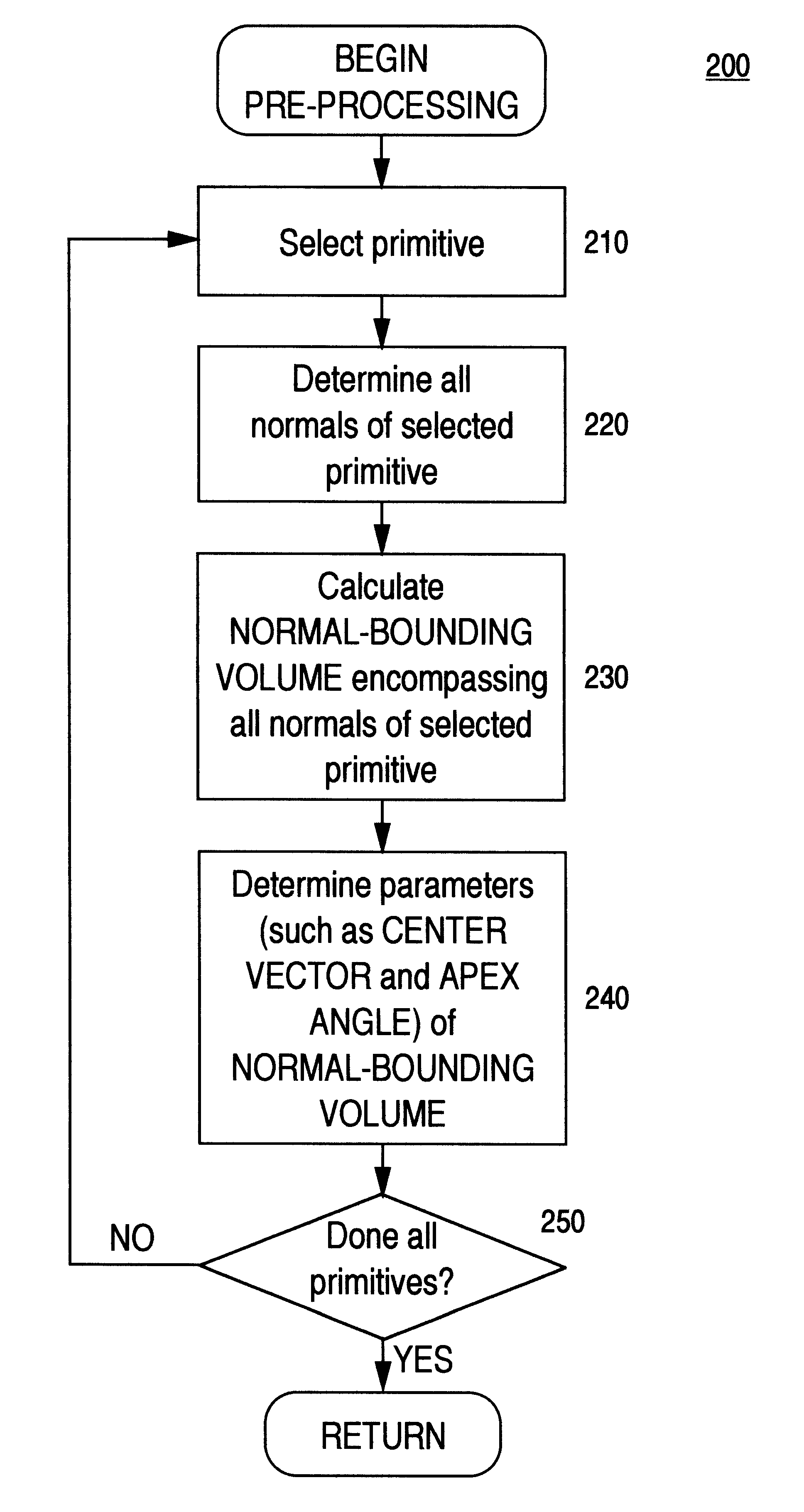
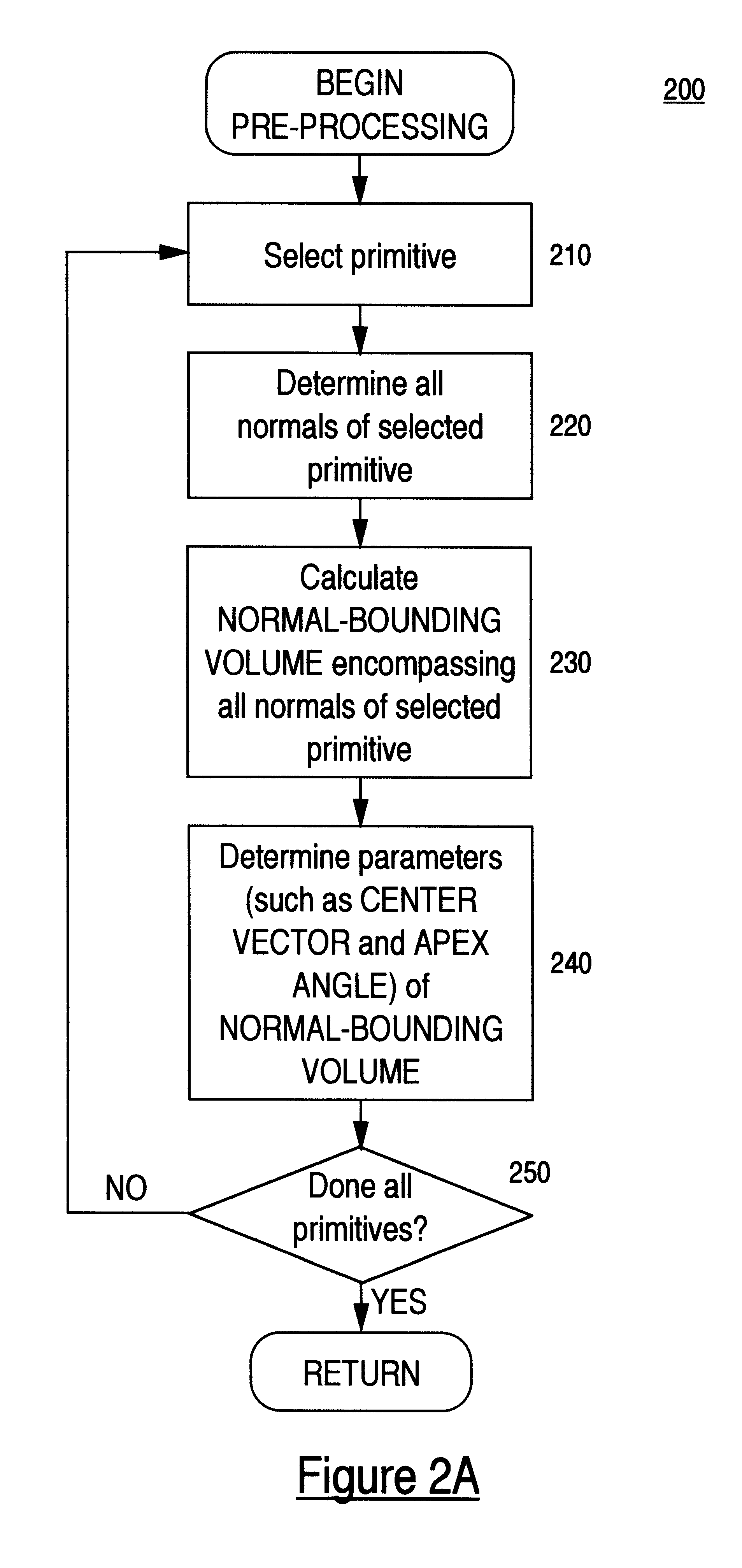
The present invention is a method and apparatus for performing visibility culling that is capable of efficiently removing backfacing polygons with minimal computational effort. More specifically, in one embodiment of the present invention, a bounding cone of all the normal vectors of each primitive in the model is calculated during a pre-processing phase. A center vector and an apex angle of the bounding cone is then stored in association with the primitive. There

Problems solved by technology

For a high resolution display (1280.times.1024) having over a million pixels, for which values must be generated for each and every pixel, displaying a three-dimensional scene on a computer system is a rather complicated task.
Processes like lighting, shading, shadowing, texture mapping, blending, etc., are particularly computation intensive, requiring a tremendous amount of processing power.
Naturally, the more complex the scene, the more processing power will be required to render that scene.
Although throughput of computer graphics systems has increased considerably in recent years, the size and complexity of three-dimension scenes have been growing even faster.
Although conventional backface culling methods are efficient in reducing the number of polygons that are sent down to the graphics pipeline, performance gain is somewhat limited as a tremendous amount of computational power is required to determined which polygons are backfacing and which polygons are visible.
The method described in Zhang et al., however, does not address the problem that each polygon is individually tested and processed.
While that method is useful in high-end graphics computer systems, it is not as useful in lower-end models where computational bandwidth is limited.

Method used


Image

  • Backface primitives culling
  • Backface primitives culling
  • Backface primitives culling

Examples


Embodiment Construction

In conventional backface culling methods, each polygon of a 3-D model is processed individually to determine whether that polygon is backfacing or is visible. Naturally, in highly-complex 3-D models having millions of polygons, such a process is nearly as computational intensive as rendering. Therefore, conventional backface culling methods do not notably increase rendering efficiency. In the present invention, however, backface culling is performed at a primitive level. In other words, backface testing is performed for each of the primitives. If it is determined that a primitive is back-facing, the whole primitive is culled. This approach is validated by the observation that primitives typically contain many polygons, and polygons within the same primitive face the same general direction in most 3-D models. The present invention provides for unique and novel methods of efficiently determining whether a primitive is backfacing. One embodiment of the present invention is illustrated ...


PUM


Abstract

A method of efficiently removing backfacing primitives from the graphics pipeline such that rendering efficiency is increased. In one embodiment of the present invention, a bounding cone of normal vectors of a primitive is first determined during pre-processing. During the rendering process, before the primitive is drawn, the bounding cone is compared with a half-space defined by a viewing vector. Primitives whose bounding cones do not intersect with the half-space will be removed from further processing. In this way, rendering efficiency is increased. In another embodiment, a normal bit-vector is used to represent normal directions of a primitive, and a visibility bit-vector is used to represent visible normal directions. In that embodiment, primitives are culled efficiently by comparing the normal bit-vector with the visibility bit-vector.

Description

The present invention relates to the field of computer generated graphics. More specifically, the present invention relates to methods of increasing efficiency of rendering two-dimensional images of three-dimensional objects in computers.Computer graphics is used in a wide variety of applications, such as in business, science, animation, simulation, computer-aided design, process control, electronic publishing, gaming, medical diagnosis, etc. In an effort to portray a more realistic real-world representation, three dimensional objects are transformed into models having the illusion of depth for display onto a two-dimensional computer screen. This is accomplished by using a number of polygons to represent a three-dimensional object. Next, a scan conversion process is used to determine which pixels of a computer display fall within each of the specified polygons. Thereupon, texture is selectively applied to those pixels residing within specified polygons. Finally, lighting, shading, s...

Claims


Application Information

Patent Timeline
IPC IPC(8): G06T15/10G06T15/40
CPCG06T15/40
Inventor HOPCROFT, MICHAEL J.SPYRIDI, ANTONIA
Owner MICROSOFT TECH LICENSING LLC
Learn More