Touch signal probe

a technology of signal probes and probes, which is applied in the direction of fluid pressure measurement by mechanical elements, electric/magnetic measurement arrangements, compasses, etc., can solve the problems of difficulty in raising the q value of a resonant vibration as compared to the conventional art 1 and inconvenient practical us

Inactive Publication Date: 2002-03-19
MITUTOYO CORP
View PDF28 Cites 24 Cited by
  • Summary
  • Abstract
  • Description
  • Claims
  • Application Information

AI Technical Summary

Problems solved by technology

According to the conventional art 1, since two pairs of linear stylus support 3 are combined and the stylus is not disposed coplanarly, it is inconvenient in practical use and size reduction thereof is difficult.
However, since a reciprocating vibration is caused to both of the X and Y axis by a single piezoelectric element, a total of four vibration system is combined, resulting in difficulty in raising Q value of a resonant vibration as compared to the conventional art 1.
Furthermore, when the stylus contacts at a high speed (more than 10mm/sec, at present), the touch signal prove is vibrated by an impact in contact, resulting in unpredictable disorder of detected amplitude

Method used


Image

  • Touch signal probe
  • Touch signal probe
  • Touch signal probe

Examples


first embodiment

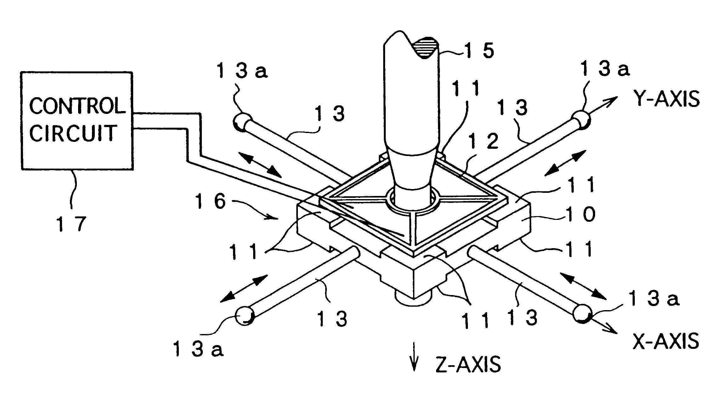
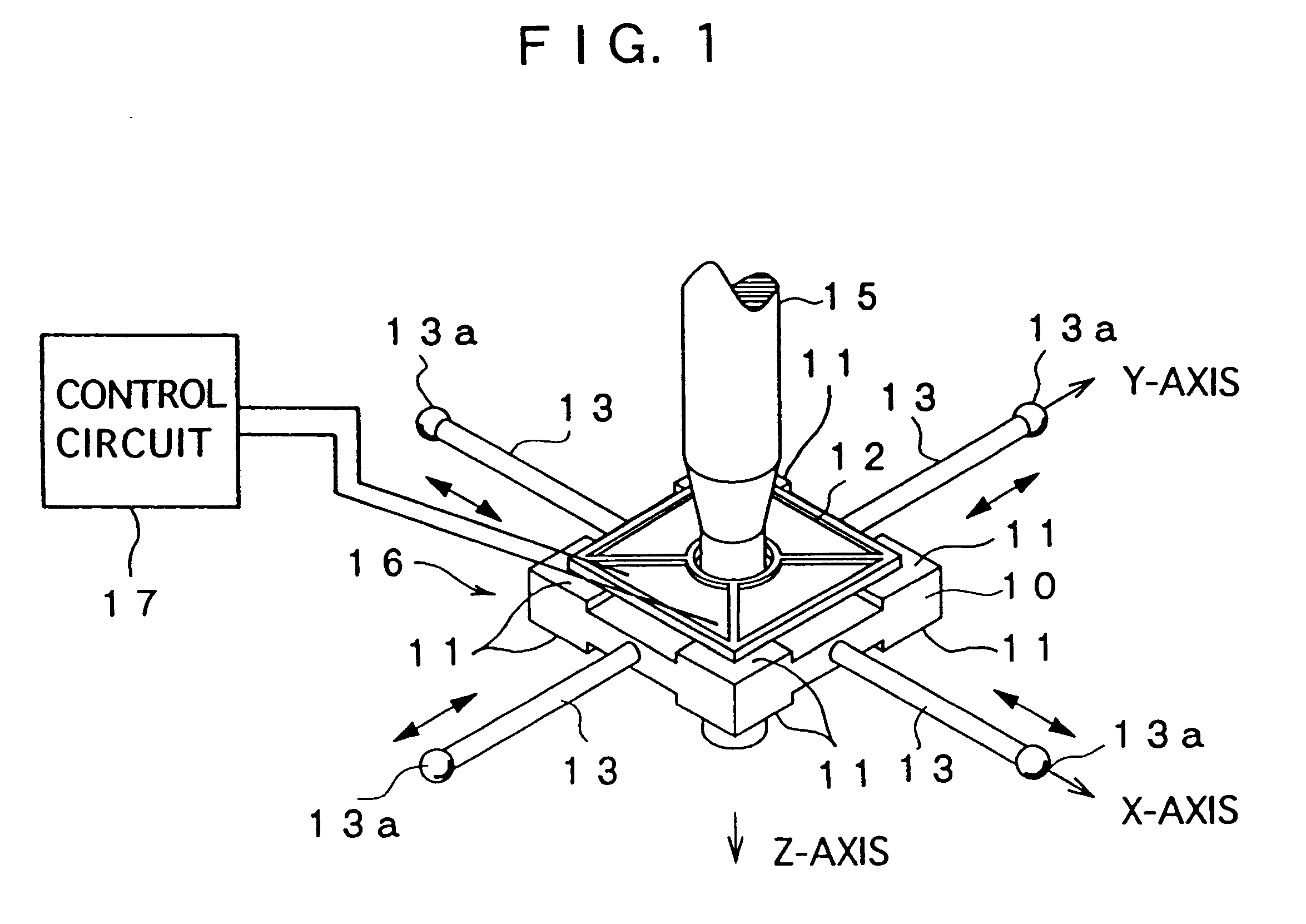
FIG. 1 to FIG. 6 show first embodiment of the touch signal probe according to the present invention.

In FIG. 1, the touch signal probe has a vibrator 16 comprising a stylus support 10 and stylus 13 attached thereto, a piezoelectric element 12 as a vibrating / detecting means for vibrating the vibrator 16 and for detecting condition of vibration which changes when the stylus 13 touches a workpiece, and a control circuit 17 for detecting the change of vibration condition of the vibrator 16 detected by the piezoelectric element 12 to transmit a touch trigger signal.

The stylus support 10 is an approximate rectangular-solid-shaped block having a center corresponding to an origin of X, Y and Z-axis and square plane perpendicular to the Z-axis. The piezoelectric element 12 is adhered to locating projections 11 projectingly provided to four corners of upper and lower plane of the stylus support (only one piezoelectric element 12 is shown in FIG. 1). A total of four styluses 13 is disposed at t...

second embodiment

of the present invention will be described below with reference to FIG. 7.

The arrangement of the second embodiment is the same as the first embodiment except for the configuration of the vibrator 26.

A vibrator 26 of the second embodiment has the stylus support 10, the stylus 13 being provided on a side of the stylus support along the X-axis, and a balance member 33 provided along either one of X-axis and Y-axis onto a side of the stylus support 10 having no stylus 13, as shown in FIG. 7.

The balance member 33 provided on the X-axis is an approximate rectangular solid block and has dynamically equivalent configuration as the stylus 13. Whether the member is dynamically equivalent or not is determined by mass, rigidity etc. of the balance member 33.

The balance member 33 fixed to both sides of the stylus support 10 along the Y-axis has the same configuration as the balance member 33 provided on the X-axis and are disposed at a regular interval with the origin as a center thereof

The piez...

third embodiment

of the present invention is shown in FIG. 8 to FIG. 11.

In these figures, a touch signal probe 81 has an approximate blockshaped stylus support 83 having a cylindrical pointed end 82A of a probe support 82 passing through at the center thereof, a vibrator 85 including four styluses 84 radially projecting in X and Y-axis direction of the stylus support 83, a vibrating piezoelectric element 86 disposed on an upper side of the stylus support 83, a detecting piezoelectric element 87 disposed on a lower side of the stylus support 83, a vibrating circuit 88 connected to the vibrating piezoelectric element 86, and a control means 89 connected to the detecting piezoelectric element 87.

The stylus support 83 is an approximately rectangular solid block of which center corresponds to an origin of the X, Y and Z-axis and having a square plane perpendicular to the Z-axis. The piezoelectric element 86 and 87 are adhered to locating projections 83A provided on four corners of upper and lower planes ...


PUM


Abstract

A vibration change is detected by a touch signal probe having a vibrator (16) composed of a stylus support (10) and a stylus (13) attached thereto, and a vibrating/detecting means (12) provided to the stylus support (10) for applying vibration to the vibrator (16) and detecting a vibration condition changing when the stylus (13) touches a workpiece. The vibrator (16) is vibrated at a frequency equivalent to secondary intrinsic frequency (w2) to make resonance and the vibration change is detected by superposing a vibration component of primary intrinsic frequency (w1). Though the vibration at the secondary intrinsic frequency (w2) has high Q value, response amplitude is small. Accordingly, the vibration change is amplified by superposing the vibration component of the primary intrinsic frequency (w1).

Description

1. FIELD OF THE INVENTIONThe present invention relates to a touch signal probe suitable for being a coordinate-measuring machine or a machine tool for measuring configuration of a workpiece. More specifically, it relates to a highly sensitive vibrating touch signal probe requiring low measurement power.2. DESCRIPTION OF RELATED ARTA height gauge (linear measuring machine), a coordinate measuring machine and a contour measuring machine are known as a measuring machine for measuring configuration and dimension of a workpiece. For measuring coordinate and position, a touch signal probe is used to the measuring machine for detecting contact of the workpiece.One detection mechanism uses a substantially cylindrical stylus having a contact portion to be abutted to the workpiece at the pointed end thereof, and a vibrating / detecting means for vibrating the stylus and detecting change of the vibration accompanied by the contact of the contact portion to the workpiece. In this arrangement, a t...

Claims


Application Information

Patent Timeline
IPC IPC(8): G01B7/00G01B7/012G01B7/008
CPCG01B7/012G01B7/002
Inventor NISHIOKI, NOBUHISAISHIKAWA, NOBUHIRO
Owner MITUTOYO CORP
Why Eureka
Try Eureka