Automated holographic-based tunnel-type laser scanning system for omni-directional scanning of bar code symbols on package surfaces facing any direction or orientation within a three-dimensional scanning volume disposed above a conveyor belt

a laser scanning system and tunnel-type technology, applied in the field of tunnel-type laser scanning systems, can solve the problems of not being able to scan bar code systems in a true omni-directional sense, and not being able to achieve true omni-directional scanning along the principal planes of a large 3-d scanning volume,

Inactive Publication Date: 2002-03-26
METROLOGIC INSTR
View PDF31 Cites 169 Cited by
  • Summary
  • Abstract
  • Description
  • Claims
  • Application Information

AI Technical Summary

Benefits of technology

Accordingly, a primary object of the present invention is to provide a novel omni-directional tunnel-type laser scann...

Problems solved by technology

While over-the-head laser scanning systems are effective in scanning upwardly-facing bar codes on conveyed objects, there are many applications where it is not practical or otherwise feasible to ensure that bar code labels are upwardly-facing during transported under the scanning station.
Notably, however, prior art tunnel scanning systems, including th...

Method used


Image

  • Automated holographic-based tunnel-type laser scanning system for omni-directional scanning of bar code symbols on package surfaces facing any direction or orientation within a three-dimensional scanning volume disposed above a conveyor belt
  • Automated holographic-based tunnel-type laser scanning system for omni-directional scanning of bar code symbols on package surfaces facing any direction or orientation within a three-dimensional scanning volume disposed above a conveyor belt
  • Automated holographic-based tunnel-type laser scanning system for omni-directional scanning of bar code symbols on package surfaces facing any direction or orientation within a three-dimensional scanning volume disposed above a conveyor belt

Examples


Embodiment Construction

Referring to the figures in the accompanying Drawings, the various illustrative embodiments of the holographic laser scanner of the present invention will be described in great detail, wherein like elements will be indicated using like reference numerals.

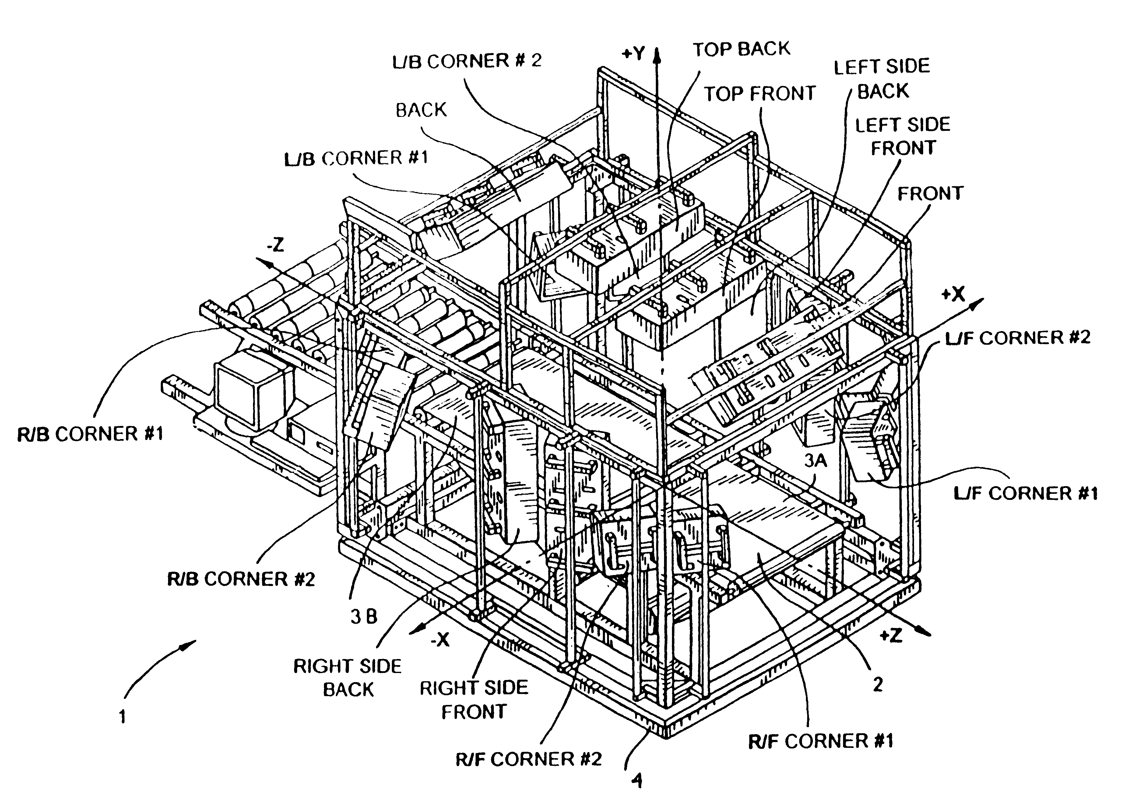
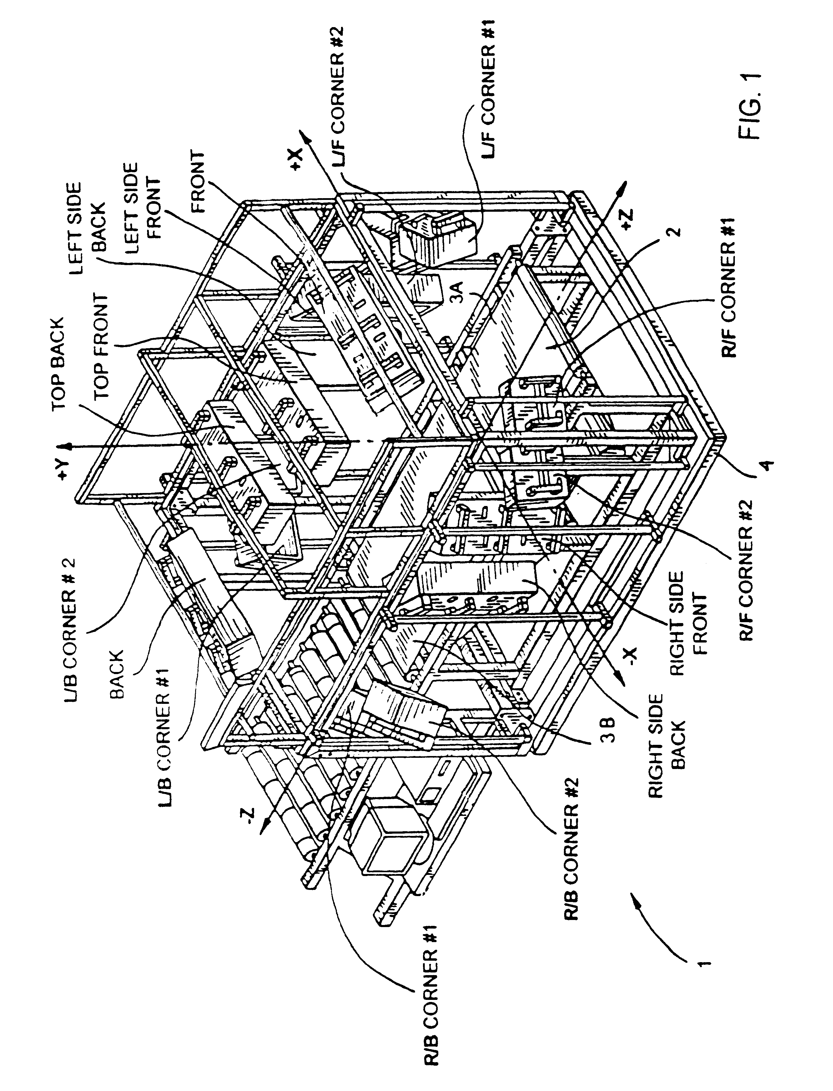
In FIG. 1, there is shown a tunnel-type laser scanning system designed to meet the needs of demanding customers, such as the United States Postal Service (USPS), who requires "hands-free" bar code (or code symbol) scanning of at least six-packages, wherein the label containing the code symbol to be read can be placed in any orientation on any one of the six or more sides of the box or container structure. As used hereinafter, the term "hands-free" shall mean scanning of bar codes on boxes or parcels that are traveling past the scanners in only one direction on some sort of conveyor system.

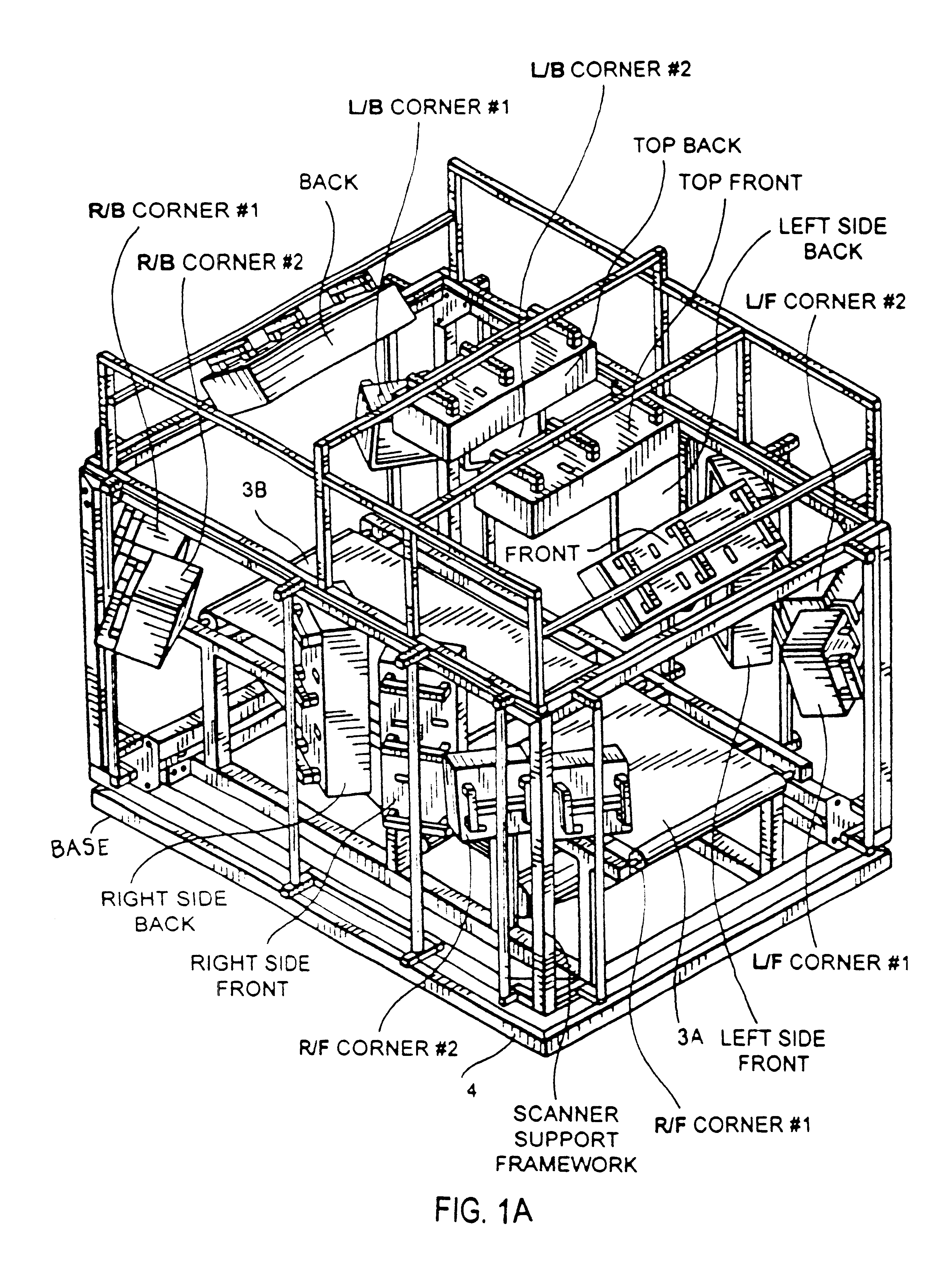
As shown in FIGS. 1 through 1D, the tunnel scanning system of the illustrative embodiment 1 comprises an arrangement of laser scanning subsystems ...


PUM


Abstract

A fully automated package identification and measuring system, in which an omni-directional laser scanning system are used to read bar codes on packages entering the tunnel, while a package dimensioning subsystem is used to capture information about the package prior to entry into the tunnel. Mathematical models are created on a real-time basis for the geometry of the package and the position of the laser scanning beam used to read the bar code symbol thereon. The mathematical models are analyzed to determine if collected and queued package identification data is spatially and/or temporally correlated with package measurement data using vector-based ray-tracing methods, homogeneous transformations, and object-oriented decision logic so as to enable simultaneous tracking of multiple packages being transported through the scanning tunnel.

Description

1. Field of InventionThe present invention relates generally to tunnel type laser scanning systems arranged about a high-speed conveyor system used in diverse package routing and transport applications, and also a method of scanning bar code symbols on surfaces facing any direction with a 3-D scanning volume disposed above the conveyor system.2. Brief Description of the Prior ArtIn many environments, there is a great need to automatically identify objects (e.g. packages, parcels, products, luggage, etc.) as they are transported along a conveyor structure. While over-the-head laser scanning systems are effective in scanning upwardly-facing bar codes on conveyed objects, there are many applications where it is not practical or otherwise feasible to ensure that bar code labels are upwardly-facing during transported under the scanning station.Various types of "tunnel" scanning systems have been proposed so that bar codes can be scanned independent of their orientation within scanning vo...

Claims


Application Information

Patent Timeline
IPC IPC(8): G02B26/10G07G1/00G06K7/10G06K7/14G06K17/00
CPCG02B26/10G07G1/0054G06K7/10G06K7/10564G06K7/10584G06K7/10594G06K7/10603G06K7/10663G06K7/10673G06K7/10693G06K7/10702G06K7/10792G06K7/10801G06K7/10811G06K7/10851G06K7/10861G06K7/10871G06K7/10881G06K7/10891G06K7/109G06K7/14G06K17/0022G07G1/0045G02B26/106G06K2207/1012G06K2207/1013G06K2207/1016G06K2207/1017G06K2207/1018
Inventor KNOWLES, C. HARRYDICKSON, LEROYGOOD, TIMOTHY A.AMUNDSEN, THOMAS C.NAYLOR, CHARLESWILZ, SR., DAVIDCARULLO, THOMAS
Owner METROLOGIC INSTR
Why Eureka
Try Eureka