Lightning protection for an active antenna using patch/microstrip elements

Inactive Publication Date: 2002-03-26
ANDREW LLC
View PDF45 Cites 16 Cited by
  • Summary
  • Abstract
  • Description
  • Claims
  • Application Information

AI Technical Summary

Benefits of technology

In an alternate embodiment of the invention, it is an objective to overlay the grounding system of conductive traces on the superstrate so that the conductive traces interact with the radiating patch to produce desirable effects in overall (azimuth) radiation pattern. Some of the desirable effects to the (azimuth) radiation pattern are: (a) to suppress backward radiation, and, (b) shaping of the pattern within the sector coverage, i.e., tailoring the pattern to roll off quicker past the sector edge.

Problems solved by technology

If a static charge develops on the (metal) patch and discharges through the aperture to the microstrip feeder line, damage to, or failure of, the active electronics connected to the microstrip feeder line is possible.

Method used


Image

  • Lightning protection for an active antenna using patch/microstrip elements
  • Lightning protection for an active antenna using patch/microstrip elements
  • Lightning protection for an active antenna using patch/microstrip elements

Examples


Embodiment Construction

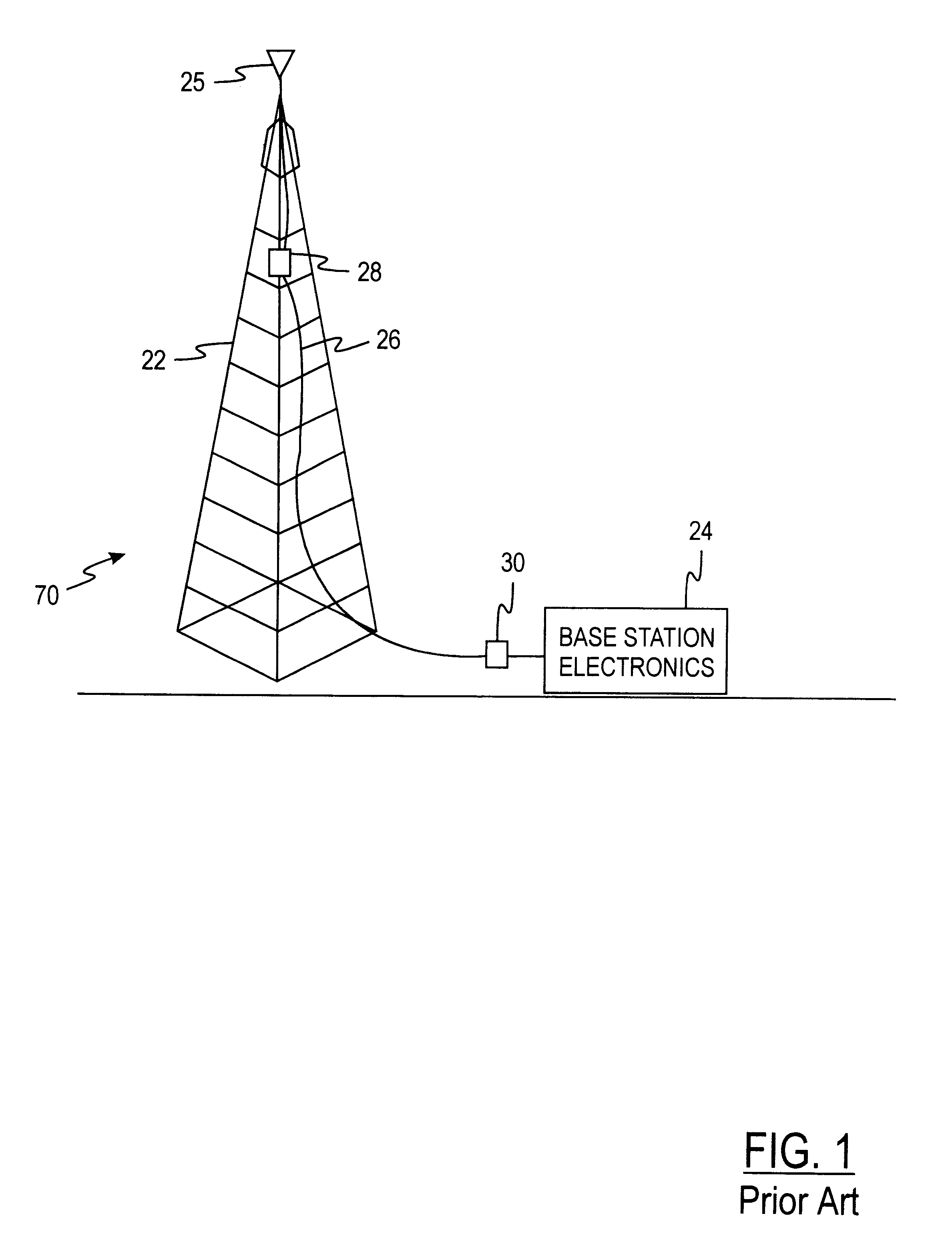
FIG. 1 shows a conventional arrangement for a Cellular or PCS base station 20 having a tower 22 with a passive antenna 25 and ground-based electronics 24 connected to the antenna 25 by an RF cable 26. Lightning arrestor(s) 28, 30 are used either after the antenna at the tower top or at the base station, before the electronics, or both. Typically, the arrestors 28, 30 are high voltage capacitors wired in series with the RF cable 26. This prevents low frequency or DC current, associated with the absorbed corona energy, from a near miss lightning strike, from traveling through the RF coaxial cable into the base station electronics.

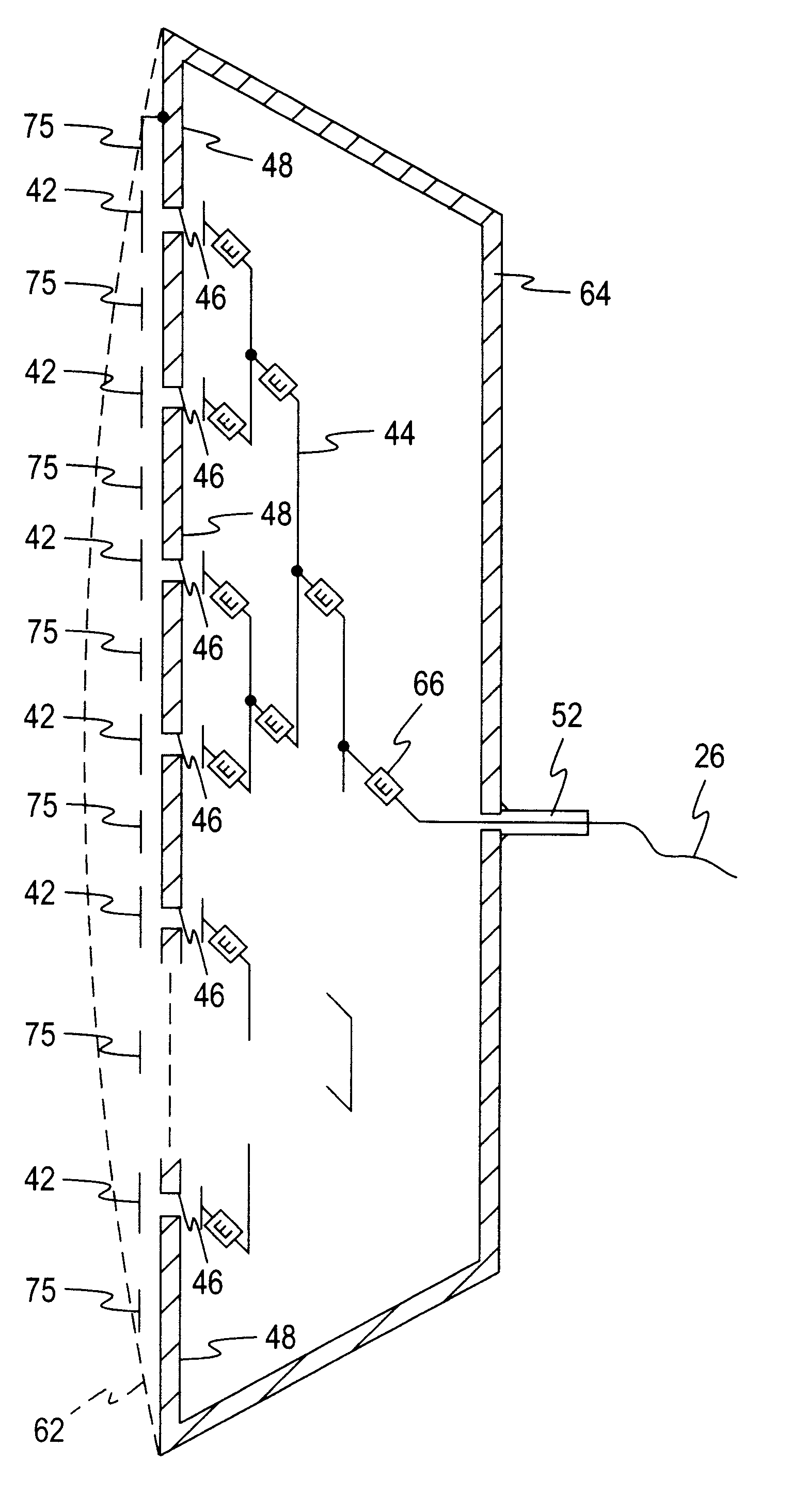
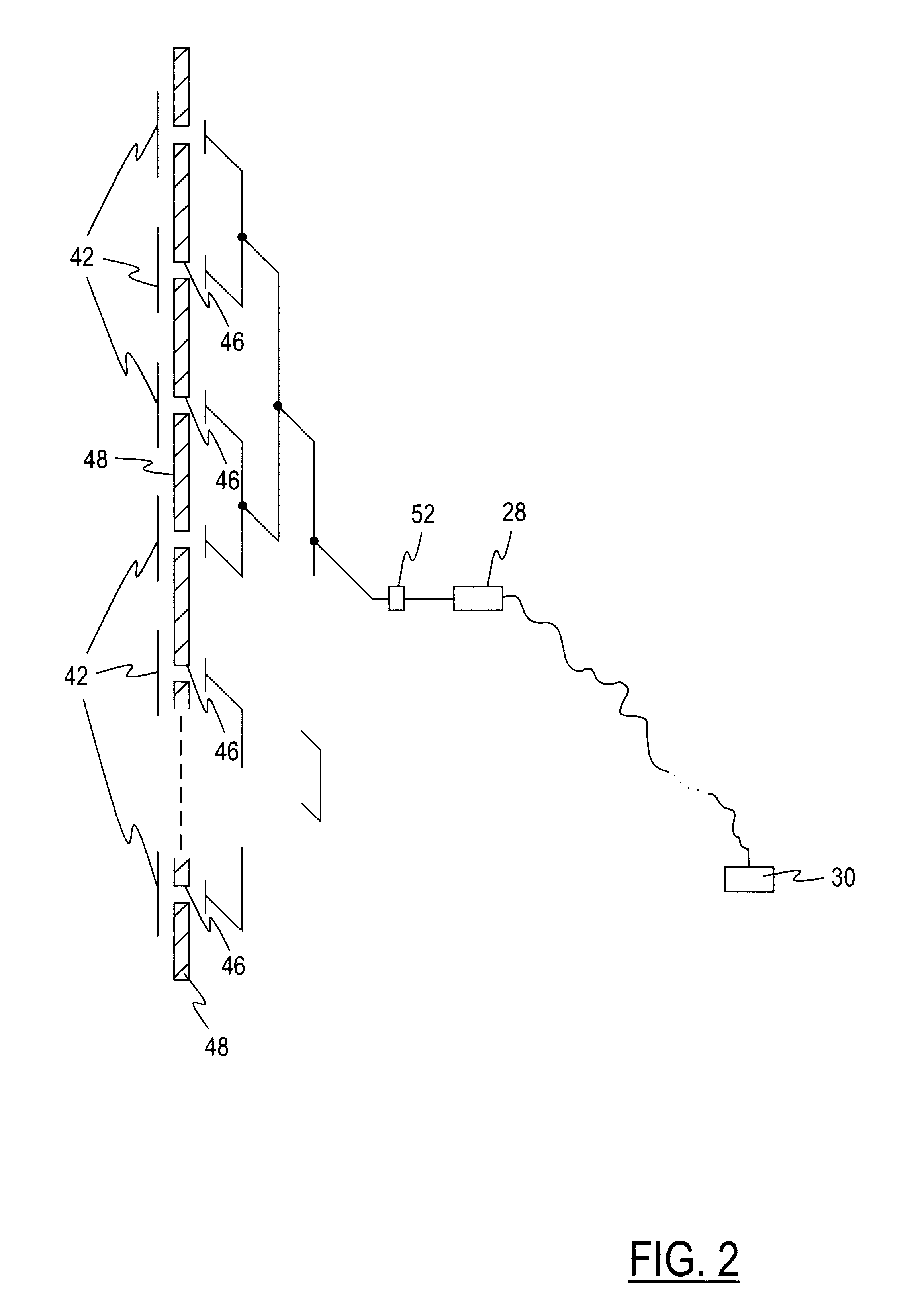
FIG. 2 shows a side view, partially in section, of a typical patch antenna system 40, using an array of patch antenna elements (or "plates") 42 and aperture coupling of the patch antenna elements 42 to a corporate feed 44, at apertures (irises) 46 in a ground plane 48. However, the invention also applies to coaxial (cable) coupling techniques. The corporate f...


PUM


Abstract

An active antenna system having lightning, corona and low frequency static energy protection includes a plurality of patch antenna elements, a feed structure operatively interconnecting the patch antenna elements, and at least one conductive drain line coupled with each of the patch antenna elements. The drain lines are coupled together at a common ground connection point.

Description

This invention is directed generally to the field of antennas for communication systems, and more particularly to a novel active antenna system using patch / microstrip antenna elements, and more particularly still, to a novel lightning, corona, and low frequency static energy protection scheme for such an antenna system.In base stations for most Cellular / PCS systems, where the antennas and cable are completely passive, lightning near strikes (or other corona discharges or high energy static) cause reliability concerns, since the antenna acts as a "sponge" to the lightning (or corona / static discharge) energy, and channels the high voltage to the sensitive electronics. Of course, in the case of direct strikes, the antenna system is typically vaporized. However, for near strikes, where the local area around the antenna is saturated with high voltage field energy, protection of the base station electronics from this energy is warranted. These systems often employ "lightning arrestor" sys...

Claims


Application Information

Patent Timeline
Patent Type & Authority Patents(United States)
IPC IPC(8): H01Q1/24H01Q23/00H01Q3/28H01Q21/08H01Q1/00H01Q21/06H01Q1/50H01Q9/04H01Q13/08H01Q25/04
CPCH01Q1/002H01Q1/246H01Q1/50H01Q23/00H01Q9/0407H01Q21/08H01Q3/28H01Q13/08
Inventor JUDD, MANO D.MONTE, THOMAS D.
Owner ANDREW LLC
Why Eureka
Try Eureka