On-vehicle disk brake lathe

a technology of brake lathe and disk, which is applied in the direction of turning machine accessories, portability lathes, manufacturing tools, etc., can solve the problem of not teaching the use of such a mechanism on the on-vehicle lathe, and achieve the effect of facilitating the measurement of disk thickness and lateral run-ou

Inactive Publication Date: 2002-04-02
BONITA IP
View PDF8 Cites 33 Cited by
  • Summary
  • Abstract
  • Description
  • Claims
  • Application Information

AI Technical Summary

Benefits of technology

It is another object of the invention to provide a compact on-vehicle disk brake lathe which can be readily adjusted.
FIG. 12 is a schematic view illustrating an embodiment of a system of the present invention which facilitates measurement of disk thickness and lateral run-out prior to machining the disk.

Problems solved by technology

While the teaching of the '457 patent offers a solution for machining of brake disks on a bench lathe, there is no teaching of the use of such a mechanism on an on-vehicle lathe.
Furthermore, the system requires the use of two sensors and a complex algorithm to ascertain the position of the cutting tips, and from this information supplemental calculations are needed to determine the thickness of the disk.

Method used


Image

  • On-vehicle disk brake lathe
  • On-vehicle disk brake lathe
  • On-vehicle disk brake lathe

Examples


Embodiment Construction

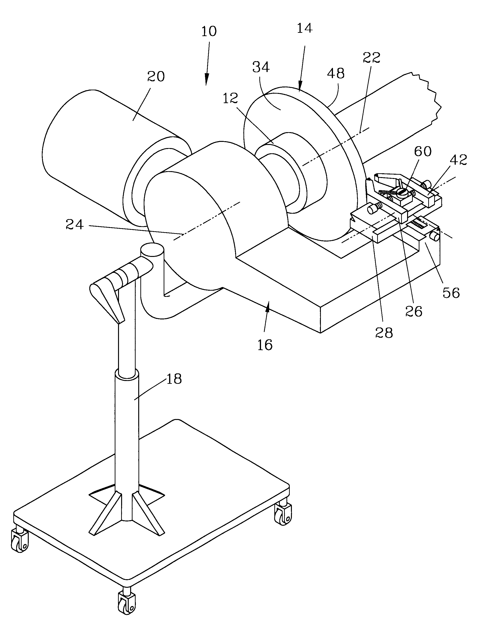
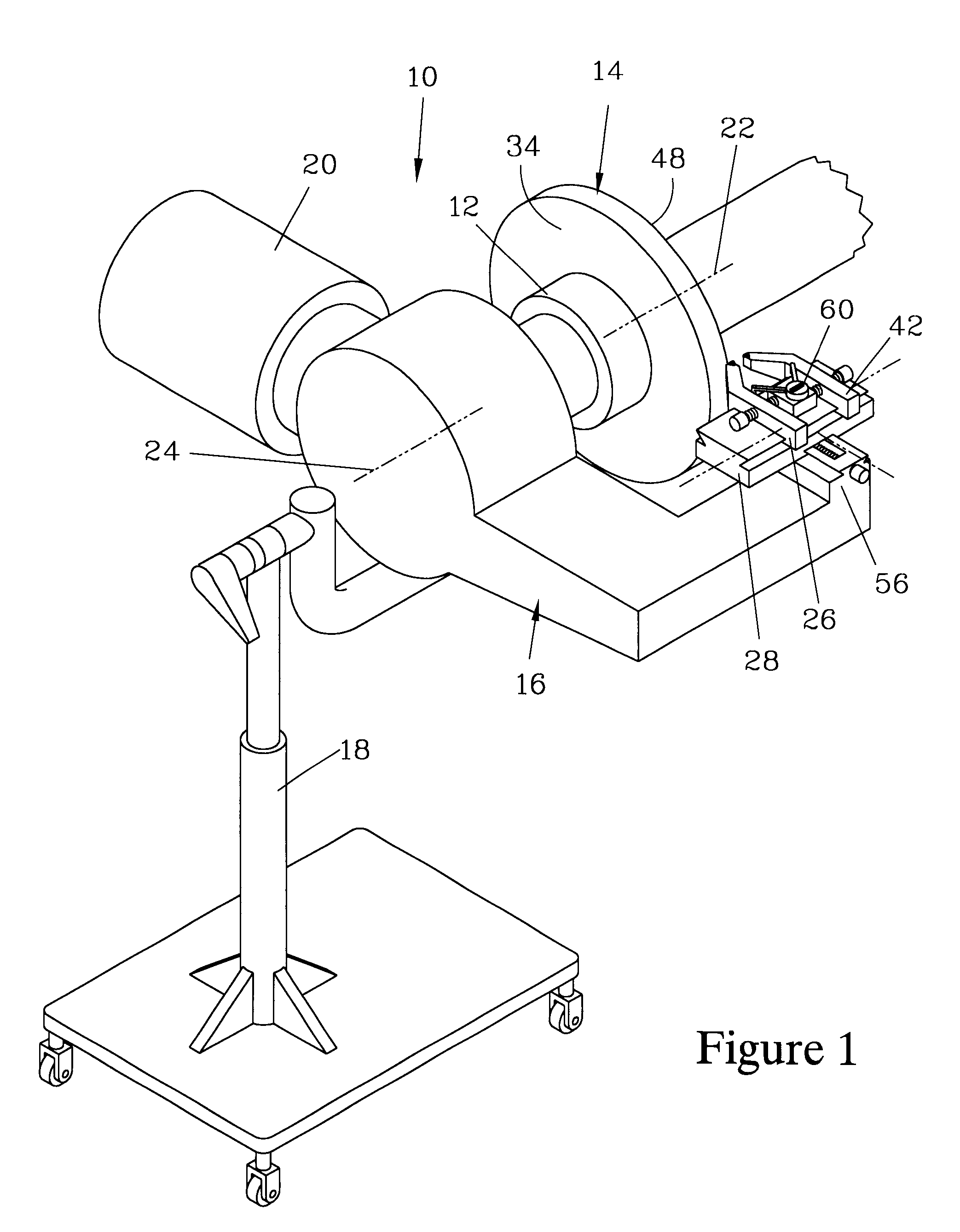
FIG. 1 is an isometric view of one embodiment of the improved on-vehicle disk brake lathe 10 of the present invention, hereinafter referred to as disk brake lathe 10. The disk brake lathe 10 attaches to a wheel hub 12 which in turn has a brake disk 14 fixably attached with respect thereto. The disk brake lathe 10 has a frame 16 which is mounted with respect to a vehicle (not shown) on which the wheel hub 12 is rotatably mounted. The frame 16 is supported by the attachment of the disk brake lathe 10 to the wheel hub 12. To prevent rotation of the disk brake lathe 10, the lathe frame 16 can be additionally supported by attachment to the vehicle or can be mounted with respect thereto via a floor stand 18. A motor 20 attached to the frame 16 rotates the wheel hub 12 and the brake disk 14 about a hub axis 22.

The disk brake lathe 10 has a lathe axis 24 which is aligned with the hub axis 22 when the disk brake lathe 10 is operated. Means to align the hub axis 22 with the lathe axis 24 are ...


PUM

PropertyMeasurementUnit
movementaaaaaaaaaa
outer diameteraaaaaaaaaa
depth of cutaaaaaaaaaa

Abstract

A disk brake lathe has a pair of tool bits mounted to tool holders which are translatable parallel to a lathe axis to adjust the separation of the tool bits from a brake disk. A displacement gauge responds to changes in the separation between the tool holders. When the tool bits are in continuous contact with the disk, the separation indicates the thickness which would result from machining the disk. This separation can be compared to a specification to determine whether to machine or discard the disk. A method for machining a disk starts by mounting and aligning the lathe to a wheel hub on which the disk is mounted. The tool bits are each advanced until they are in continuous contact the disk surfaces, when the separation of the tool bits is measured and preferably compared to a specification. When the tool bits are sequentially advanced, variation in the separation can be used to determine depth of cut for each tool bit. A system employing a brake lathe has a microprocessor which receives signals responsive to the separation between the tool bits of the lathe. One or more contact sensors indicate contact of the tool bits with the other tool bit or the brake disk, and the microprocessor can implement instructions to practice the above method. A surface displacement gauge can be employed to allow the system to measure the thickness and lateral run-out of the disk prior to machining.

Description

The present invention relates to an on-vehicle disk brake lathe which can provide an indication of the depth of cut on the surfaces of the disk, determine the lateral runout of the disk, and monitor the thickness of the disk which will result when the disk is machined.There are a variety of measuring devices that are currently used in combination with bench lathes that allow monitoring of the surface being cut or, alternatively, measuring the position of the cutting tip. U.S. Pat. No. 5,765,457 provides an example of a bench lathe which provides a measuring system for determining the position of one or more cutting tips relative to a reference position that allows one to back out the depth of cut. The '457 patent also teaches that, when the positions of both cutting tips are measured relative to a reference plane, one can calculate the thickness of the disk and determine a priori whether the disk is sufficiently thick that it can be machined to bring it into specification.While the ...

Claims


Application Information

Patent Timeline
Patent Type & Authority Patents(United States)
IPC IPC(8): B23Q17/20B23Q17/22B23B5/04B23B5/00
CPCB23B5/04B23Q17/20B23Q17/22B23B2270/14Y10T82/10Y10T82/21Y10T82/16016
Inventor GREENWALD, CHRISTOPHER L.HASTINGS, JEFFREY P.
Owner BONITA IP
Why Eureka
Try Eureka