System for working the surface of a road

a technology for working surfaces and roads, applied in the direction of cutting machines, roads, constructions, etc., can solve the problems of excessive installation costs, failure of such components, and inability to adapt to large-scale activities

Inactive Publication Date: 2002-04-02
CANNIZZO STEVEN +1
View PDF13 Cites 16 Cited by
  • Summary
  • Abstract
  • Description
  • Claims
  • Application Information

AI Technical Summary

Benefits of technology

Now in accordance with the present invention, a system is provided for working the surface of a road to carry out variety of the aforementioned functions to that road, including the installation of reflectors, the formation of rumble strips, the boring of holes, cutting of line striping, pot hole milling by or for a variety of other functions that cut or work the road surface where the working apparatus requires some vertical adjustment to determine the desired depth of penetration. The system is defined in combination with a vehicle having a motor powered vertically movable rear lift gate which, in use, defines a vertically displaceable substantially horizontal platform. The particular rotating road working apparatus is secured to the upward facing surface of the lift gate with the apparatus itself being mounted on a rotatable drive shaft extending laterally of the gate. In one of the various embodiments, a series of cutting blades c

Problems solved by technology

While towed carts and the like are quite suitable for providing small numbers of installations, they do not lend themselves to large scale activities.
The use of such rudimentary apparatus in turn leads to excessive installation costs for the many road building and installation agencies which seek to exploit the many safety advantages of the in-road installed type of light

Method used


Image

  • System for working the surface of a road
  • System for working the surface of a road
  • System for working the surface of a road

Examples


Embodiment Construction

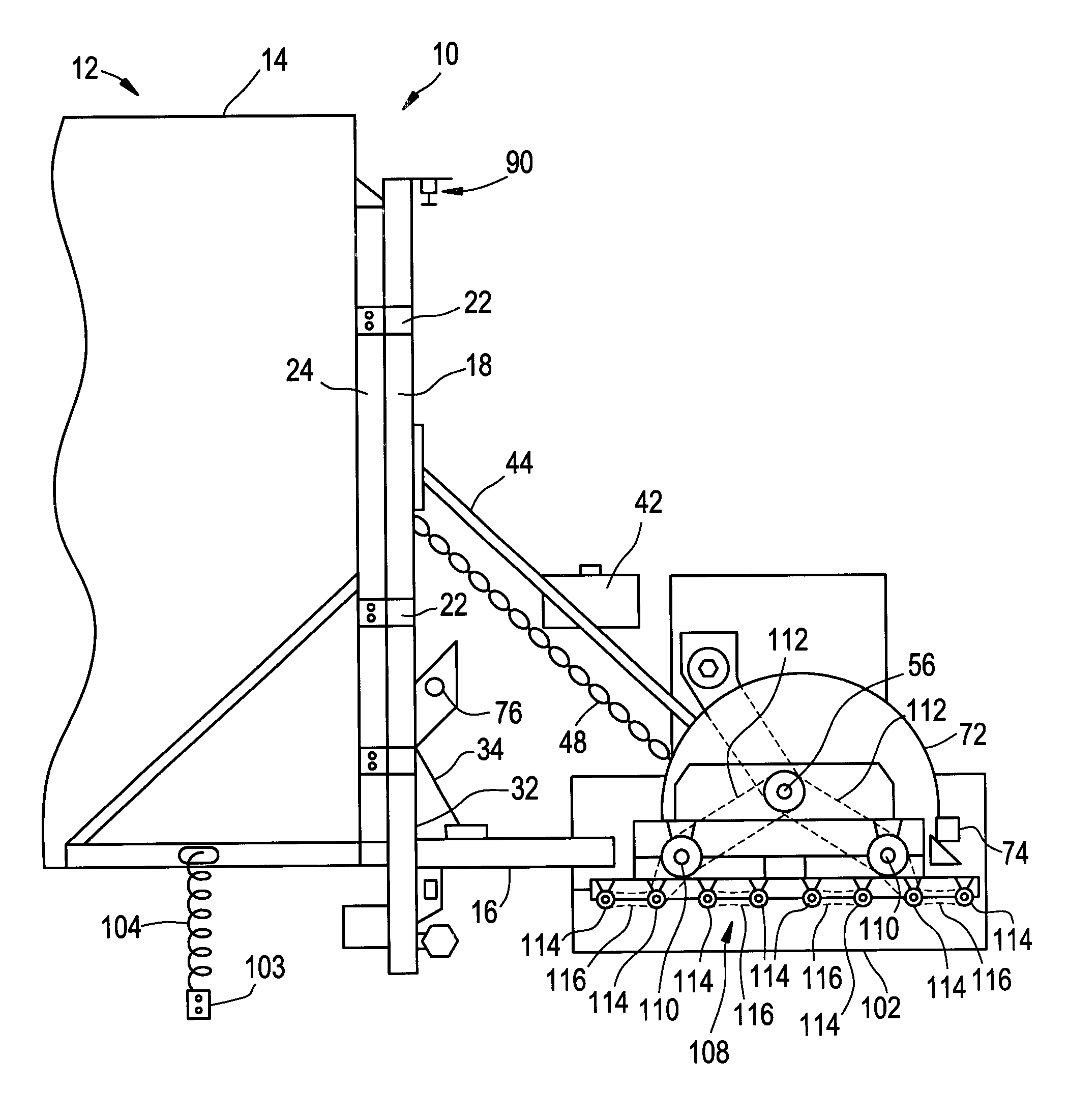
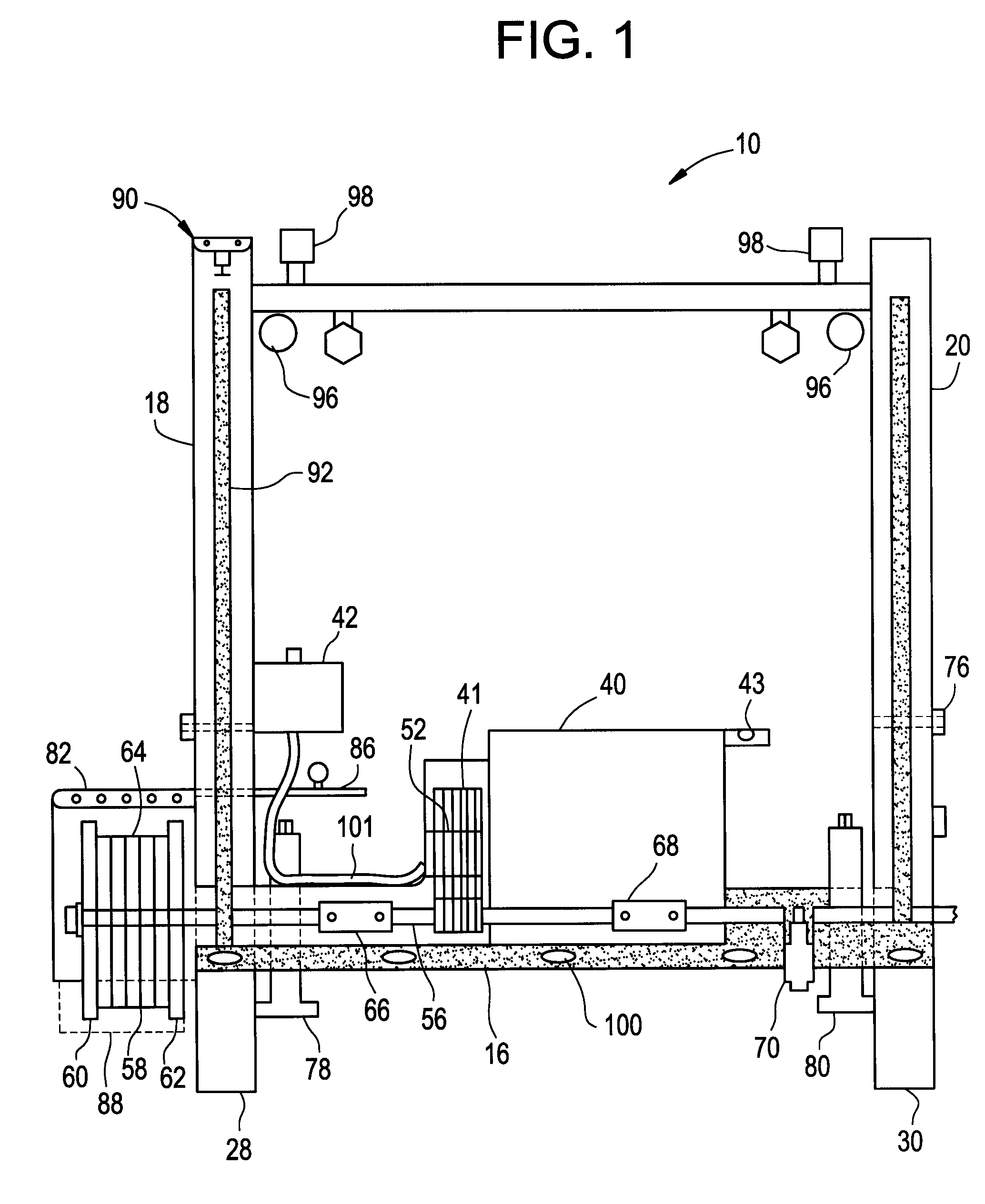
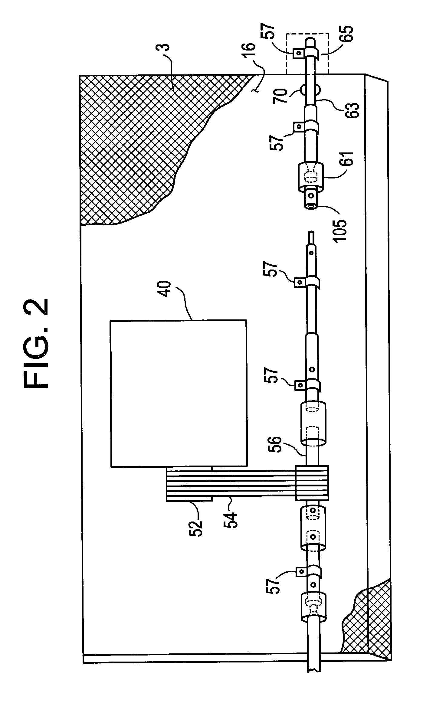
FIG. 1, which may be viewed simultaneously with FIGS. 2, 3, 4 and 5 schematically depicts a system 10 in accordance with the present invention for producing cavities in a road surface into which reflective road markers are to be received. System 10 is a combination which includes a vehicle 12 such as a truck, a portion of which is shown at 14 (FIGS. 3 and 4), which vehicle is provided with a lift gate 16. The lift gate 16 is per se a well-known device for use with trucks and other vehicles to aid in loading and unloading. In use, such a conventional lift gate is placed (if not already so oriented) in a horizontal plane to define a platform for receiving loads. The lift gate is movable vertically between desired positions of elevation so that loads may be moved between the truck bed and a loading platform or other surface. This vertical movement is accomplished by electric or hydraulic motors which are actuated by an operator. Various types of lift systems are known for lift gates. A...


PUM


Abstract

An assembly is provided for excavating cavities in a road surface for a variety of purposes, among them, the formation of rumble strips, the installation of light reflective road markers, the milling of potholes, boring of holes for various purposes and the like. The system is used in combination with a vehicle having a motor powered vertically movable rear lift gate which in use defines a vertically displaceable substantially horizontal platform. A cutting apparatus is secured to the upward facing surface of the lift gate with the actual cutting portion being mounted on a rotatable drive shaft extending laterally of the gate, such that the cutting portion projects at least partially below the bottom surface of the lift gate, whereby with the gate in a lowered position, the cutting portion can engage the surface of the road on which the vehicle resides. A motor is secured to the upper surface of the gate powers the drive shaft. The vertical position of the lift gate is adjustible with respect to the surface of said road, to control the depth of cut and thus the degree of excavation produced by the cutting apparatus.

Description

This invention relates generally to road construction and maintenance apparatus, and more specifically relates to a system for working or generally cutting into the surface of a road, that is, to produce cavities or openings in the pavement surface for various purposes, among them, the installation of reflectors, the formation of rumble strips in the road surface, the boring of holes in the road surface, the cutting of a striping, the milling of potholes or generally to otherwise physically affect the road surface.BACKGROUND OF INVENTIONThere are many operations that are needed to be performed through working or in some way cutting into or affecting the surface of a road. For example, light reflective lane and border markers have come into ever increasing use on modem roads and highways. These well-known devices are installed in the pavement at spaced intervals extending in the direction of vehicular travel, so that a motorist traveling under darkened or inclement weather conditions...

Claims


Application Information

Patent Timeline
IPC IPC(8): E01C23/088E01C23/00E01C23/09
CPCE01C23/088E01C23/0993E01C23/0946
Inventor CANNIZZO, STEVENROBINSON, LEROY I.
Owner CANNIZZO STEVEN
Why Eureka
Try Eureka