Lead wire connection method for touch panel

a technology of lead wires and touch panels, which is applied in the direction of coupling device connections, emergency connections, instruments, etc., to achieve the effect of increasing the connection strength of lead wires

Inactive Publication Date: 2013-12-24
NISSHA PRINTING COMPANY
View PDF23 Cites 64 Cited by
  • Summary
  • Abstract
  • Description
  • Claims
  • Application Information

AI Technical Summary

Benefits of technology

[0021]Further, the metal-pin is equipped with the pin-head having a diameter larger than the outer diameter of the pin-shaft, thereby allowing the metal-pin to be connected to the conductor wire part of the lead wire in a wide range. Further, the pin-head is locked at the edge of the metal-pin fixing hole in the lead wire, thereby allowing the inserted depth of the pin-shaft inserted into the through hole of the lower electrode plate to be controlled.
[0022]In the present invention, concave groove are formed in the pin-shaft of the metal-pin, and when the pin-shaft is inserted into the through hole while applying an ultrasonic vibration and a pressure thereto, it is preferable to guide the melted portion of the wall surface of the through hole in the concave groove. Hereby, an anchoring effect can be obtained with respect to the metal-pin.
[0027]According to the present invention, the method for connecting read wires to the touch panel increasing the connecting strength of the lead wires can be provided without performing a significant design change.

Problems solved by technology

However, in such a method for taking out a signal by the use of the connecting metal fixtures 55, there is an inconvenience, in that when a touch panel is mounted on a device such as an interface board or a liquid crystal display, four connecting pins for inserting the connecting metal fixtures 55 into positions corresponding to the through holes 51d to 51g must be erectly provided in the device, thereby requiring a change in lead wire connecting structure for both the touch panel and the above-mentioned device.

Method used


Image

  • Lead wire connection method for touch panel
  • Lead wire connection method for touch panel
  • Lead wire connection method for touch panel

Examples


Embodiment Construction

[0037]Hereinafter, on the basis of an embodiment shown in drawings, the present invention will be explained in detail.

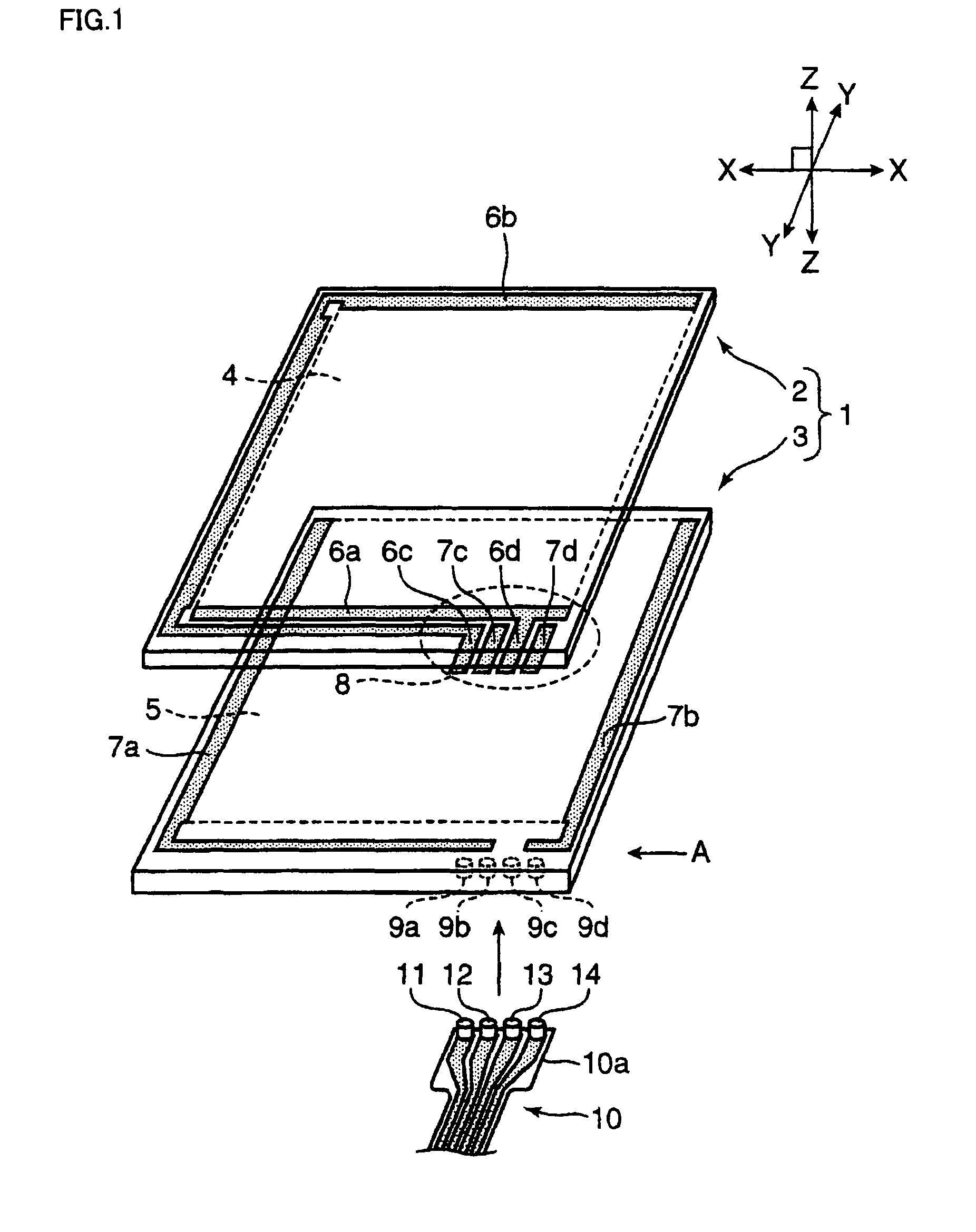
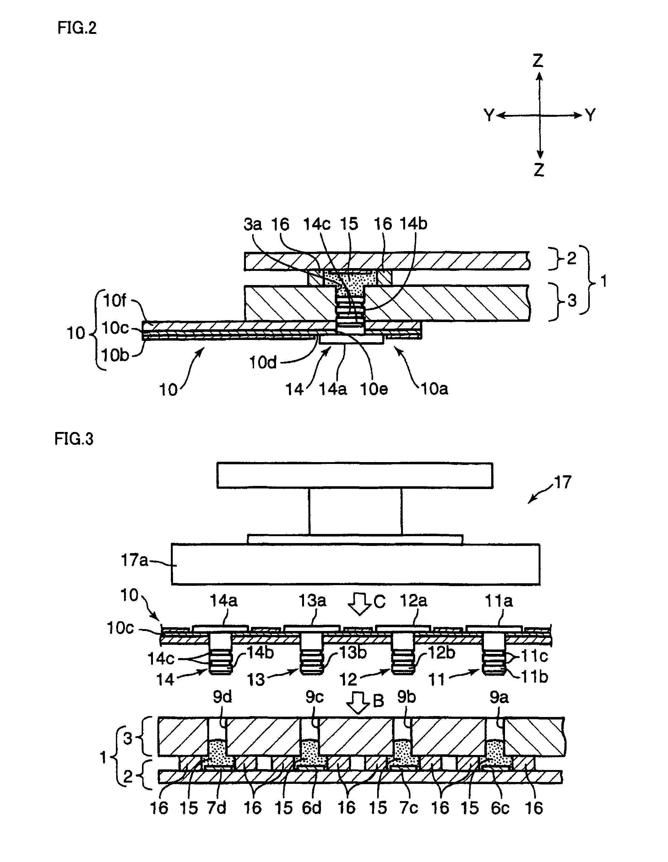
[0038]FIG. 1 is an exploded view showing a configuration of a touch panel to which the present invention is applied.

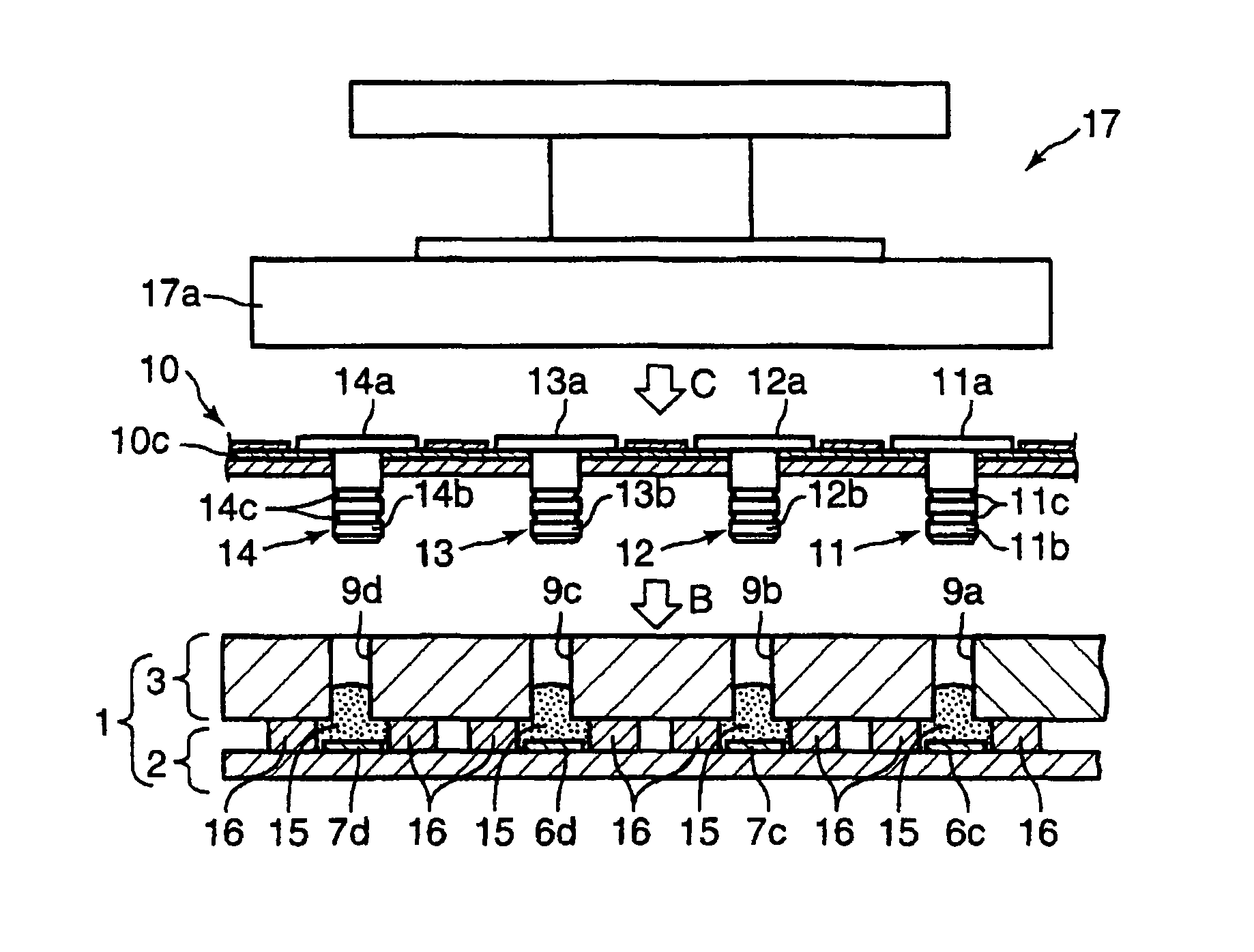
[0039]In the figure, a touch panel 1 has an upper electrode plate 2 made of a flexible transparent insulated film, for example, a polyethylene terephthalate film, and a lower electrode plate 3 made of a non-flexible glass plate, or an engineering plastic such as polycarbonate-base, polyamide-base, polyether ketone-base, or a plastic plate such as acryl-base, polyethylene terephthalate-base, polybutylene terephthalate-base, or a laminated plate thereof. The two plates adhere to each other oppositely through a spacer (not shown).

[0040]Formed on an inner surface of each of the electrode plates 2, 3 are resistive films 4, 5 with ITO (Indium-Tin Oxide) and the like by spattering or vacuum evaporation.

[0041]Strip-shaped electrodes 6a, 6b made of a silver past...


PUM


Abstract

In a method for connecting lead wires to a touch panel, the method includes the steps of: providing through holes 9a to 9d the number of which corresponds to the number of electrode ends by perforation in a lower electrode plate 3; using a metal-pin 11 having a pin-shaft 11b and a disk shaped pin-head 11a with a diameter larger than an outer diameter of the pin-shaft; inserting the pin-shaft 11b into a metal-pin fixing hole formed corresponding to the through hole 9a at a circuit 10c in a connector tail of a lead wire 10, whereby the pin-shaft 11b is erectly provided on the connector tail of the lead wire 10; and inserting the pin-shafts 11b to 14b into the through holes 9a to 9d, and in addition, electrically connecting the pin-shaft inserted into a lower electrode plate 3 through a conductive adhesive 15 to electrode ends 6c, 7c, 6d, 7d.

Description

TECHNICAL FIELD[0001]The present invention relates to a method for connecting lead wires to a touch panel used for inputting coordinates on a screen in a mobile phone, a PDA (Personal Digital Assistance) as a personal portable information terminal, a car navigation system, and the like.BACKGROUND ART[0002]Conventionally, a touch panel display formed by arranging a touch panel on a liquid crystal display in a lamination manner has been widely used for small equipment such as a mobile phone and a PDA, because a screen and a coordinate input means are collectively provided for saving of a space.[0003]As the above-mentioned touch panel, a resistive film type that is simple in structure, thin in thickness and excellent in mass production has generally used. A configuration thereof is as follows: an upper electrode plate having a flexibility as an operation side and a lower electrode plate as a fixed side are oppositely arranged with a predetermined gap by a spacer, and electric circuits ...

Claims


Application Information

Patent Timeline
Patent Type & Authority Patents(United States)
IPC IPC(8): G06F3/045
CPCG06F3/045H01R12/62H05K3/368G06F2203/04103H01H2207/01H01H2207/014H01R4/04H05K3/321H05K3/361H05K2201/10303H05K2201/10424H05K2201/10871G06F3/04164H01R12/71
Inventor NISHIKAWA, KAZUHIROKAI, YOSHIHIRONAKAMURA, KAZUTO
Owner NISSHA PRINTING COMPANY
Why Eureka
Try Eureka