Foam-concrete rebar tie

a technology of foam-concrete rebar and rebar ties, which is applied in the direction of building reinforcements, constructions, building components, etc., can solve the problems of poor tension of concrete and prior art failure to present a proper system, apparatus and method for properly positioning and orienting rebar at a proper position, so as to prevent rotational and longitudinal movement and add rigidity to the structure

Inactive Publication Date: 2009-09-17
NELSON STEVEN J
View PDF32 Cites 60 Cited by
  • Summary
  • Abstract
  • Description
  • Claims
  • Application Information

AI Technical Summary

Benefits of technology

[0005]The structure in one form described in this disclosure is a holding member having an extension portion, a base portion, and a stirrup portion. The extension portion is configured to be inserted into a rigid construction material such as a block of foam. The extension portion in one form comprises a plurality of base members with barbs which extend radially outward from the longitudinal axis of the extension portion. These barb members are constructed to add rigidity to the structure, and assist in proper positioning within the rigid construction material. These barb members are especially helpful in preventing rotational and longitudinal movement of the holding member in relation to the foam. In one form, a plurality of barb members extend from the barb members to further maintain the position of the extension within the first construction material. The extension portion may be directly coupled to or formed with the stirrup portion, or an intermediate base portion may be provided between the two. This base portion can provide a stop which will limit the depth to which the extension member can be inserted into the foam. All three elements may also be formed as a unitary structure, say of a polymer or metal.

Problems solved by technology

In general, concrete is very poor in tension, and having an insert therein, for example a metallic member such as a longitudinally extending piece of rebar, significantly enhances the strength of the concrete structure.
The prior art has failed to present a system, apparatus and method for properly positioning and orienting rebar at a proper depth within the outer concrete perimeter region.

Method used


Image

  • Foam-concrete rebar tie
  • Foam-concrete rebar tie
  • Foam-concrete rebar tie

Examples


Embodiment Construction

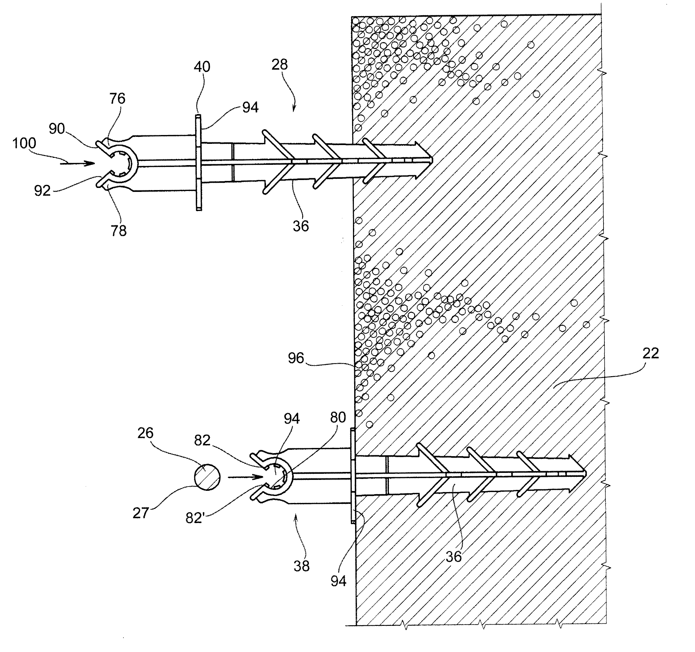
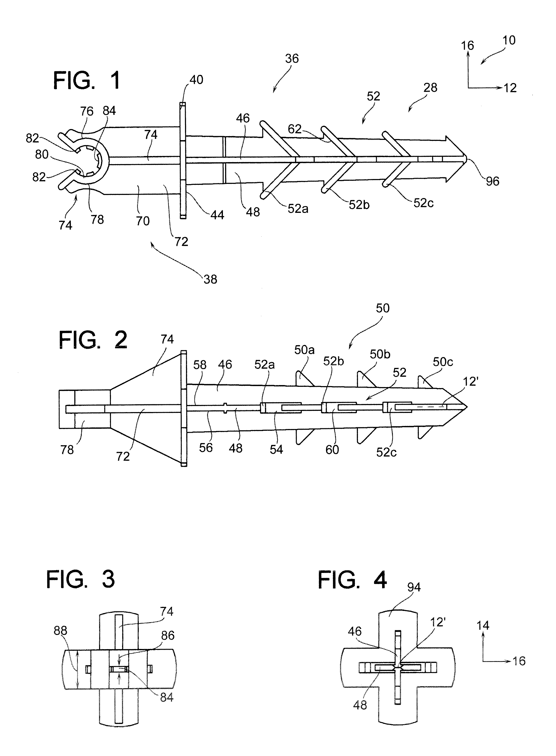
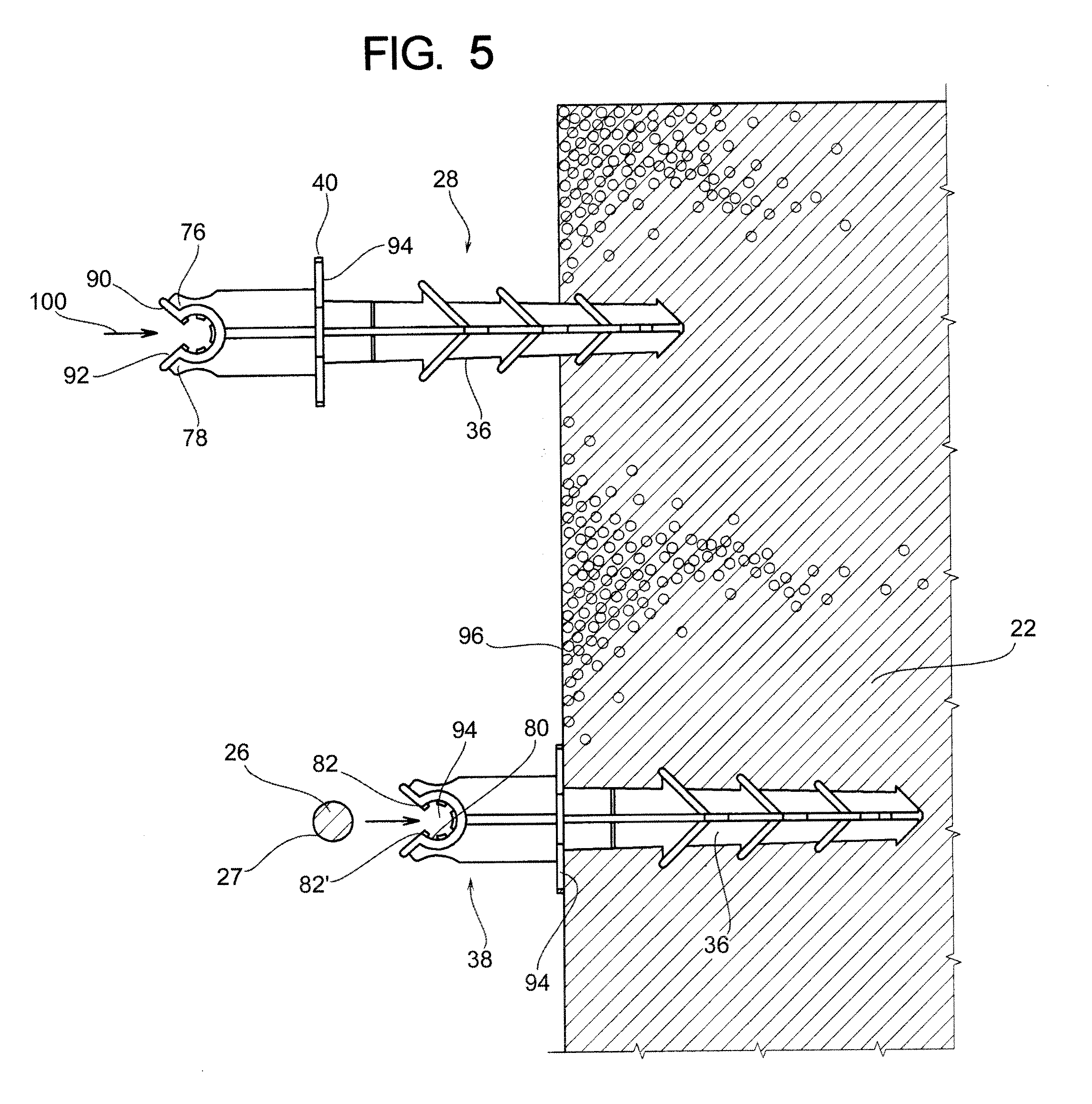
[0015]As shown in FIG. 7, there is an environmental view of a foam concrete structure 20. In general, the foam concrete structure 20 comprises a foam material 22 and a concrete perimeter 24. Further comprising the foam concrete structure 20 are tensile stress members such as rebars and rebar holding members 28. Further, in one form of manufacture, an outer mold member 30 can be utilized to hold the concrete 24 in its position while in an uncured state. This outer mold member 30 can either be a part of the veneer of the structure, or be removed from the concrete perimeter 24 once the concrete cures or otherwise is sufficiently rigid to hold its stationary form.

[0016]Therefore, it can be appreciated that the tensile stress member 26, which is most commonly rebar at the time of this writing, is positioned at a substantially center region 32 within the concrete perimeter 24. This positioning allows the rebar 26 to engage the surrounding concrete so as to transfer force thereto, so when ...


PUM

PropertyMeasurementUnit
perimeteraaaaaaaaaa
perimeteraaaaaaaaaa
distanceaaaaaaaaaa

Abstract

A fastener is disclosed having a an extension portion configured to be inserted into a first construction material such as foam, and having a stirrup portion configured to retain portion of a second construction material, such as rebar at a distance from the first construction material. A third construction material such as concrete can then be inserted (poured) in contact with the first construction material and surrounding the second construction material such that the second construction material is not directly in contact with the first construction material.

Description

BACKGROUND OF THE DISCLOSURE[0001]Foam concrete structures are utilized in various capacities ranging from concrete stairs, drive ways, ramps, floating docks, precast walls, abutments, retaining walls with lightweight fill load distribution slabs, roadways and applications for concrete foam systems such as Geofoam™ and other applications for concrete foam structures. In general, a foam concrete structure has a central region comprised of foam material which may be expanded polystyrene (EPS) or extruded polystyrene (XEPS) with a perimeter portion of concrete therearound. Oftentimes, a tensile strength member such as rebar is positioned within the concrete. At present time, rebar, which is comprised of steel or other iron-based compositions, is a primary form of enhancing the strength of concrete to reinforce concrete structures. In general, concrete is very poor in tension, and having an insert therein, for example a metallic member such as a longitudinally extending piece of rebar, ...

Claims


Application Information

Patent Timeline
Patent Type & Authority Applications(United States)
IPC IPC(8): E04C5/16
CPCE04C5/20
Inventor NELSON, STEVEN J.
Owner NELSON STEVEN J
Why Eureka
Try Eureka