Connector with articulated latch

a technology of articulated latches and connectors, applied in the direction of optical elements, coupling device connections, instruments, etc., can solve the problems of difficult backward withdrawal of connectors from receptacles, particularly difficult tasks, and awkward feel of connectors, so as to reduce the axial force of connectors and minimize the net rotation of latches

Inactive Publication Date: 2002-04-02
COMMSCOPE TECH LLC
View PDF10 Cites 118 Cited by
  • Summary
  • Abstract
  • Description
  • Claims
  • Application Information

AI Technical Summary

Benefits of technology

The present invention is directed to a connector having a latching mechanism, which, when actuated, does not introduce a significant forward force to the connector. To this end, the latching mechanism comprises an articulated latch having joints configured such that the moment on one side of the actuation point is substantially reduced if not canceled by an opposing moment on the opposite side of the actuation point. This way, the net rotation on the latch is minimized. Minimizing the net rotation on the latch reduces the axial force on the connector.

Problems solved by technology

This is a particularly challenging task because the light-carrying region (core) of an optical fiber is quite small, for example, in single-mode optical fibers the core diameter is about 8 microns.
Although the LC connector is effective in providing alignment of two very small optical fiber cores, it tends to have an awkward feel when being released from a mating connector.
More specifically, when releasing the latch, there is a tendency to push the connector forward thereby making the backward withdraw of the connector from the receptacle more difficult.
Thus, the action of the user depressing the latch by using the tab head 124 will cause the connector to be pushed forward thereby making release from the associated connector more difficult.
Therefore, as the user actuates the latch, a forward axial force is applied to the connector making its withdrawal from the receptacle more difficult.

Method used


Image

  • Connector with articulated latch
  • Connector with articulated latch
  • Connector with articulated latch

Examples


Embodiment Construction

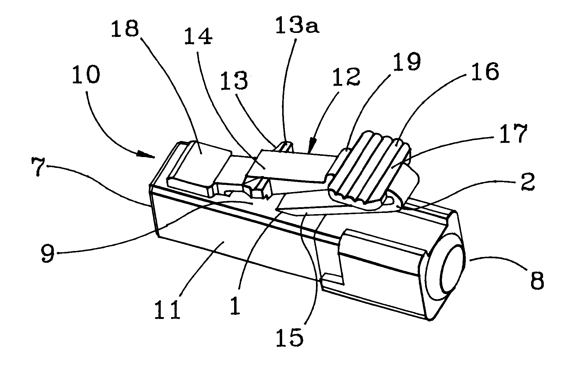
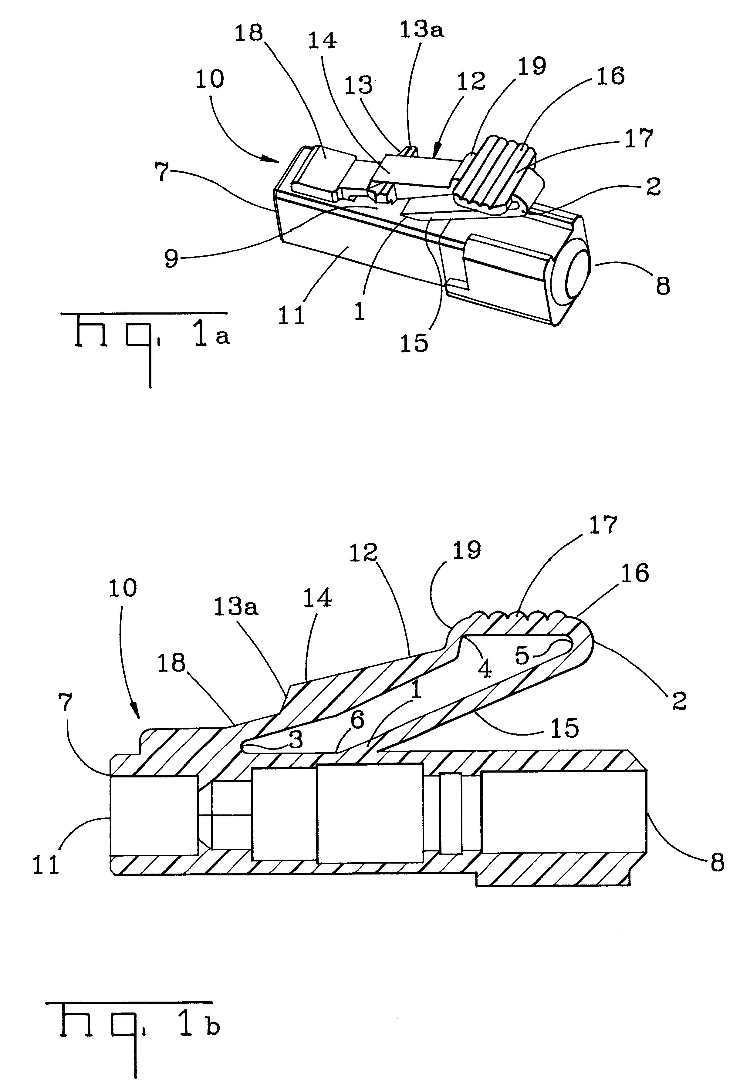
The latch mechanism of the present invention is suitable for any connector that effects the connection of a signal-carrying medium to a mating connector. As used herein the term "signal-carrying medium" refers to any conventional material used for carrying signals and includes optical waveguides, such as glass optical fibers and plastic optical fibers, and electrical conductors, such as copper and aluminum. The term "mating connector" as used herein refers broadly to any structure configured to receive a connector and to couple the signal-carrying medium contained therein with a device or another signal-carrying medium. Mating connectors include, for example, connector couplings, adaptors, simplex / duplex ports, backplane interfaces, passive devices, such as attenuators and multiplexers / dimultiplexers, and active devices, such as transceivers and simplex transmit / receive devices.

Although the present invention may be practiced with any connector, for illustrative purposes, the descrip...


PUM


Abstract

A connector for engaging a mating connector comprising: (a) a housing having a longitudinal axis and a front and back orientation and being adapted for receiving a signal carrying medium; and (b) an articulated latch connected to the housing at one or more primary joints and having a plurality of sections, wherein at least one of the sections has an engagement structure which is adapted to engage a corresponding structure on the mating connector such that the connector and the mating connector cannot be separated without actuating the latch, and wherein at least two sections are connected at a secondary joint, the primary and secondary joints being configured such that, when an actuating force is applied to the articulated latch, a moment on one side of the actuation point is reduced by an opposing moment on the opposite side of the actuation point, thereby reducing the axial force on the connector.

Description

The present invention relates generally to connectors and, more specifically, to a connector for use with optical fibers or electrical conductors and having a latch to effect its disengagement with a mating connector.BACKGROUND OF INVENTIONOptical fiber connectors are an essential part of substantially any optical fiber communication system. For instance, such connectors are used to join segments of fiber into longer lengths, to connect fiber to active devices such as radiation sources, detectors and repeaters, and to connect fiber to passive devices such as switches and attenuators. The principal function of an optical fiber connector is to hold two optical fiber ends such that the core of one of the fibers is axially aligned with the core of the other fiber. This way, all of the light from one fiber is coupled to the other fiber. This is a particularly challenging task because the light-carrying region (core) of an optical fiber is quite small, for example, in single-mode optical ...

Claims


Application Information

Patent Timeline
Patent Type & Authority Patents(United States)
IPC IPC(8): H01R13/627G02B6/38
CPCG02B6/3879H01R13/6272G02B6/3893
Inventor MANNING, RANDY MARSHALL
Owner COMMSCOPE TECH LLC
Why Eureka
Try Eureka