Power supply system and state of charge estimating method

a power supply system and state-of-charge technology, applied in the direction of electric/fluid circuit, final product manufacturing, transportation and packaging, etc., can solve the problems of affecting the life of the battery, reducing the charging efficiency, and consuming heat at a time of deceleration of the automobil

Inactive Publication Date: 2002-04-02
SHIN KOBE ELECTRIC MASCH CO LTD
View PDF1 Cites 16 Cited by
  • Summary
  • Abstract
  • Description
  • Claims
  • Application Information

AI Technical Summary

Problems solved by technology

However, the energy at a time of deceleration of the automobile is consumed as heat.
In the lead-acid battery, when the charged rate reaches a current value of 1 CA or more, a decomposition reaction of water which is a sub-reaction at a time of charging is accelerated so that the charging efficiency is reduced, thereby affecting the life of the battery adversely.
Therefore, it is difficult to allow such large current charging in a conventional lead-acid battery.
However, the charge reaches the constant voltage region rapidly, loss of the regenerative energy increases.
Also, in a case that a large current charging is allowed, there occurs a drawback in that the temperature of the lead-acid battery ascends and the life of the storage battery may be decreased in an assumption that the battery is mounted in the engine room (atmospheric temperature of 60.degree. C.) of an automobile.
However, such an error factor that a long time is required until the open circuit voltage of the lead-acid battery is made stable is large, so that a sufficient control accuracy of the state of charge in the lead-acid battery could not have been achieved.
Therefore, there is a problem in that, since the distance between the external terminals are made close to each other to be shortened, leakage current becomes easy to flow between the 36V terminals.
Further, when the 36V lead-acid battery is connected in the power system (42V system), erroneous connection may occur between a plus cable and a minus cable.
For this reason, leakage current flow becomes difficult to occur and erroneous connection between a plus cable and a minus cable becomes difficult to occur when connection of the secondary battery for a running vehicle is performed in the power system 10.

Method used


Image

  • Power supply system and state of charge estimating method
  • Power supply system and state of charge estimating method
  • Power supply system and state of charge estimating method

Examples


Embodiment Construction

Next, the text results of charging tests of power systems of examples manufactured according to the above-mentioned embodiments will be explained. Incidentally, the test results of charging tests of power systems of comparative examples manufactured for comparison will also be explained.

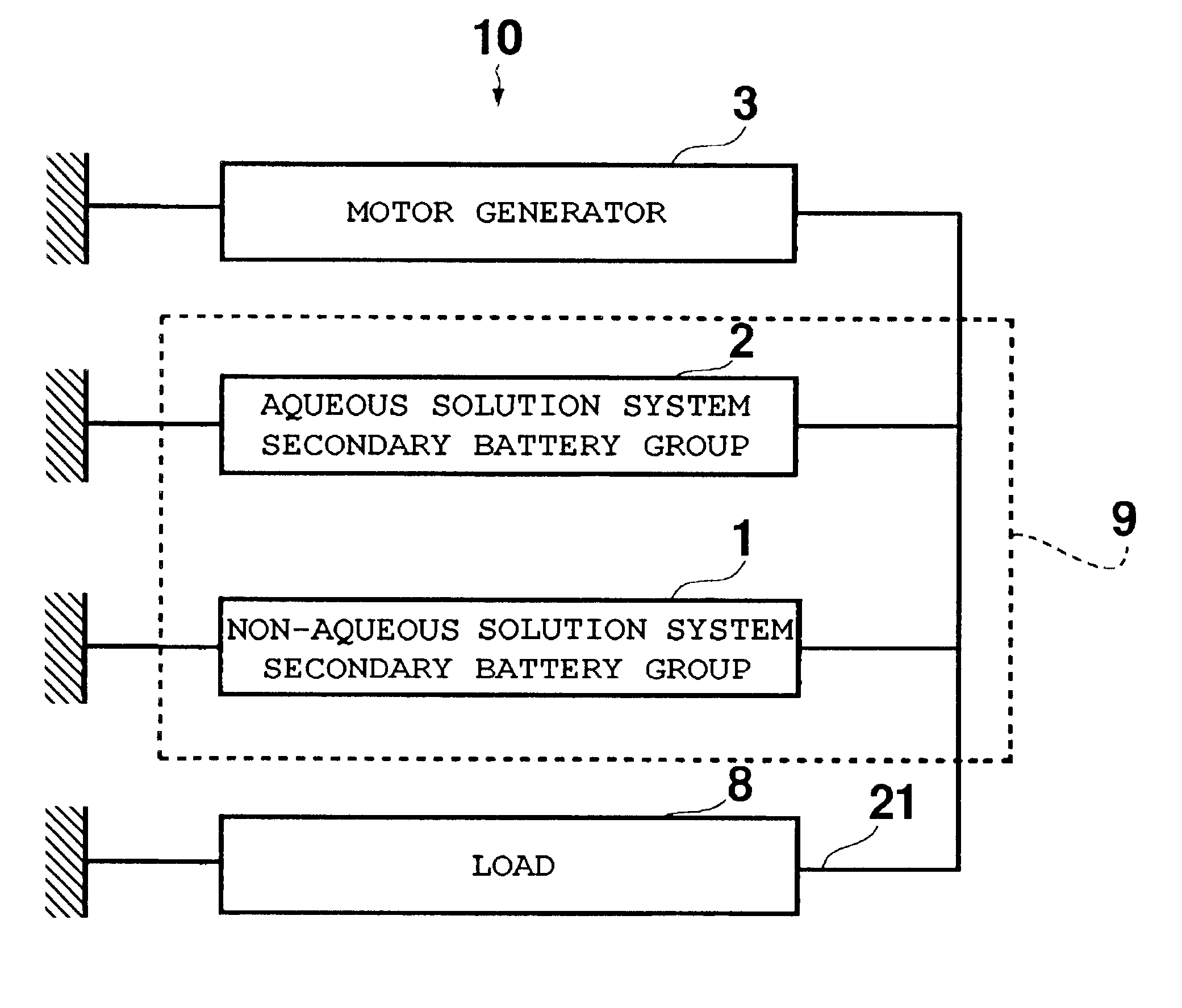
In the power system 10, charging tests were performed regarding Example 1 where 10 lithium ion secondary batteries (3.6V-3.5 Ah) connected in series were used as the non-aqueous solution system secondary battery group 1 and Example 2 where 11 lithium ion secondary batteries (3.6V-3.5 Ah) connected in series were used as the non-aqueous solution system secondary battery group 1. A charging test was also performed regarding Comparative example 1 where only a 36V system control valve type lead-acid battery (36V-18 Ah) comprising 18 cells was used as a conventional power system.

FIG. 10 shows a relationship between fifth second battery voltages and charging rates of Example 1, Example 2 and Comparative ex...


PUM


Abstract

A power system where energy generated at a deceleration time of a running vehicle such as an automobile can be accepted as regenerative energy sufficiently and safely is provided. In a power system 10, a non-aqueous solution system secondary battery group 1 where 10 to 11 lithium ion secondary battery cells are connected in series and an aqueous solution system secondary battery group 2 where 18 control valve type lead-acid battery cells are connected in series are connected in parallel. The battery capacity of the non-aqueous solution system secondary battery group 1 is smaller than that of the aqueous solution system secondary battery group 2. The non-aqueous solution system secondary battery group 1 and the aqueous solution system secondary battery group 2 are charged at a current value of 7C or less from a motor generator 3, and the ratio of the charged current value of the aqueous solution system secondary battery group 2 to the charged current value of the non-aqueous solution system secondary battery group 1 is 0.05 to 1.00.

Description

This application is based upon a Japanese patent application, serial number 2000-093726, entitled "Power system For Running Vehicle", of Ookoshi et al., filed on Mar. 30, 2000, Japanese patent applications, serial numbers 2000-128741, 2000-128742 and 2000-128743 entitled "Power system For Running Vehicle", of Shimoura, Ookoshi et al., filed on Apr. 28, 2000, a Japanese patent application, serial number 2000-209284, entitled "Power system For Running Vehicle", of Okuda et al., filed on Jul. 11, 2000, a Japanese patent application, serial number 2000-228688, entitled "Power system For Running Vehicle and State of Charge Estimating Method for the System", of Ookoshi et al., filed on Jul. 28, 2000, a Japanese patent application, serial number 2000-231620, entitled "Power system For Running Vehicle", of Okuda et al., filed on Jul. 31, 2000, and a Japanese patent application, serial number 2000-231621, entitled "Secondary battery For Running Vehicle", of Maeda et al., filed on Jul. 31, 20...

Claims


Application Information

Patent Timeline
Patent Type & Authority Patents(United States)
IPC IPC(8): H02J7/14B60R16/02B60R16/03
CPCH02J7/1423B60R16/03H02J2310/46Y02P70/50
Inventor OOKOSHI, TETSUROMINOURA, SATOSHIHIRASAWA, TOKIYOSHIMORIMOTO, YOSHINARISHIMOURA, ICHIROOKUDA, YOSHIHISAMAEDA, KENICHIYAMADA, KEIZO
Owner SHIN KOBE ELECTRIC MASCH CO LTD
Why Eureka
Try Eureka