
Energy management system and method for an extruded aluminum vehicle subframe

Inactive Publication Date: 2002-04-09
FORD GLOBAL TECH LLC +1
View PDF18 Cites 59 Cited by
  • Summary
  • Abstract
  • Description
  • Claims
  • Application Information

AI Technical Summary

Benefits of technology

Upon a vehicle impact generating an impact force on the transverse beam above a predetermined force, the fastener deforms the deformable barrier and is displaced longitudinally from the fastener hole into the relief opening. The deformable attachment bracket, and the attached subframe, drop down beneath the vehicle chassis during the impact event, with the subframe then free to translate longitudinally relative the vehicle chassis during the crash event, safely away from the vehicle occupant compartment.

Problems solved by technology

Moreover, traditional subframe bolt shearing as an energy absorbing structure has been found impractical in certain applications, particularly with the trend toward lightweight vehicle structural materials, such as aluminum.
But the use of shearing steel bolts in such application is nearly impossible when used in conjunction with relatively softer and less stiff structures, such as aluminum, that are becoming more and more prevalent in vehicle structures.
However, such a load will collapse the typical overall aluminum structural assembly prior to any shearing of the bolts.
Thus, where the longitudinal load members are manufactured from aluminum to carry and transfer load to the main vehicle support structure, the shear load level obtained with traditional shear bolts as used with steel structures is simply too high to render shearing of the bolts feasible.

Method used


Image

  • Energy management system and method for an extruded aluminum vehicle subframe
  • Energy management system and method for an extruded aluminum vehicle subframe
  • Energy management system and method for an extruded aluminum vehicle subframe

Examples


Embodiment Construction

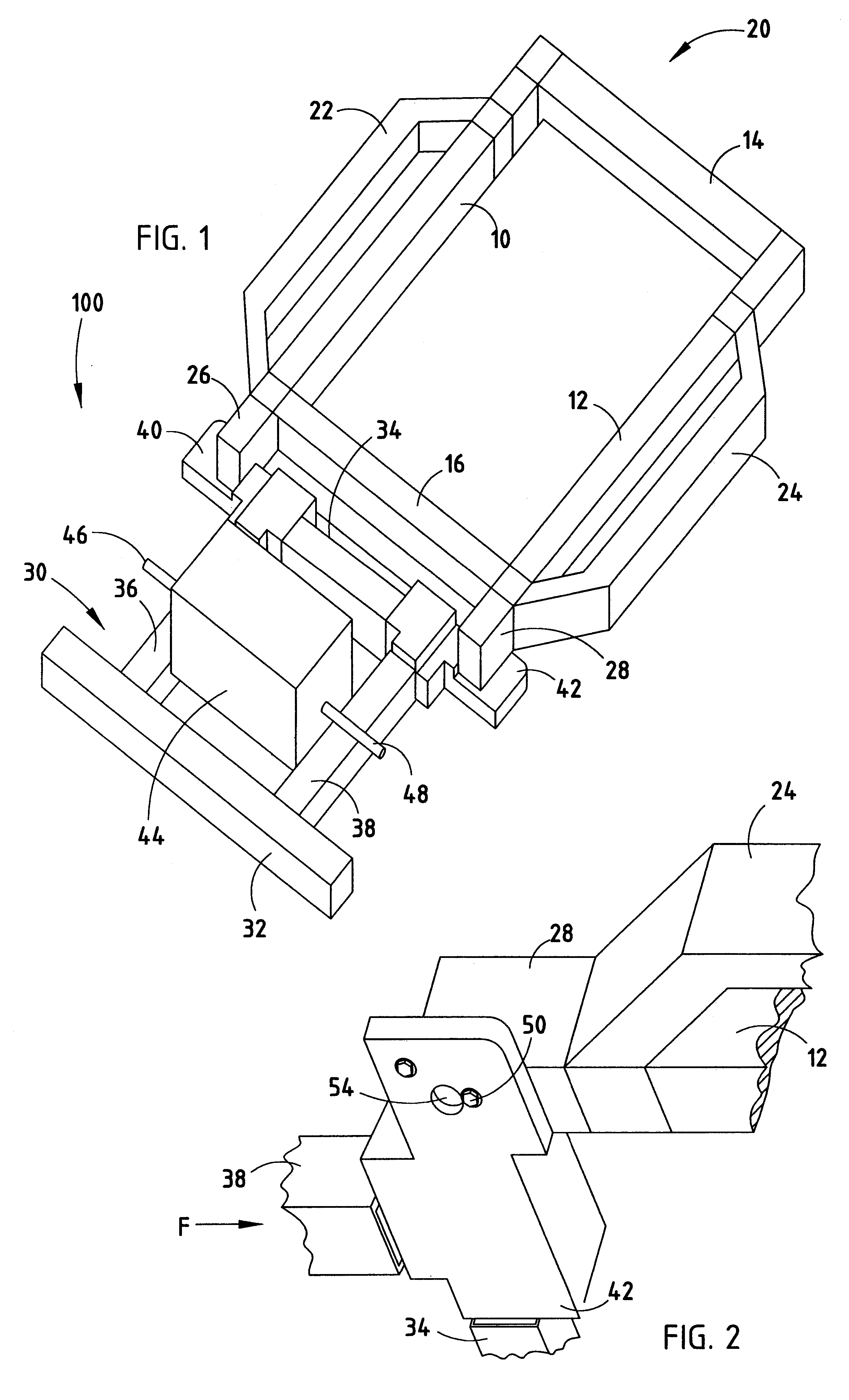
The best mode for carrying out the invention is presented in terms of the preferred embodiment wherein similar reference characters designate corresponding features throughout the figures of the drawings. Referring now to the drawings, particularly FIG. 1, there is shown the energy management system for absorbing and directing vehicle kinetic energy during an impact event of a motor vehicle according to the present invention, represented by front body structure 100. A main vehicle support structure is conceptually shown as formed by right and left longitudinal members 10 and 12 connected by rear and front transverse members 14 and 16 to form a basic chassis or frame 20. As used herein, "chassis" is intended to refer to any main vehicle support structure to which body components and structures may be attached, such as a traditional vehicle frame formed from parallel and interconnected rails, as well as any integral body structure that may be used to support drivetrain, steering and s...


PUM


Abstract

An energy management system and method for absorbing and directing kinetic energy during an impact event of a motor vehicle includes a vehicle subframe 30 attached to a vehicle chassis 20, with a pair of deformable attachment brackets 40 and 42 interposed therebetween. The deformable attachment brackets 40 and 42 are preferably fixedly attached to the subframe 30 and removably attached to the vehicle chassis 20 via fasteners 50 extending through a fastener hole 52 in each of the attachment brackets 40 and 42. A relief opening 54 is proximate to and aligned with the fastener hole 52, the relief opening 54 being larger than the fastener 50. A deformable barrier 56 disposed between the fastener hole 52 and relief opening 54 may be provided with a slot 58 extending between the fastener hole 52 and relief opening 54. Upon an impact generating an impact force above a predetermined force, the fastener 50 deforms the deformable barrier 56, whereby the deformable attachment bracket 40 and 42 is displaced longitudinally such that the fastener 50 is relocated from the fastener hole 52 into the relief opening 54. The fastener 50 slides out of the relief opening 54 and the subframe 30 drops beneath the vehicle chassis 20, whereby the subframe 30 translates longitudinally relative the vehicle chassis 20 during the crash event, safely away from the vehicle occupant compartment.

Description

This invention relates to an energy management system and method for absorbing and directing kinetic energy during an impact event of a motor vehicle. More particularly, the present invention relates to a deformable aluminum attachment bracket for attaching an extruded vehicle subframe to a vehicle chassis, where the attachment bracket is purposely deformed upon experiencing an impact load above a predetermined level, allowing the subframe to drop down and below the vehicle chassis during an impact event.DESCRIPTION OF THE RELATED ARTThe controlled management of kinetic energy remains a primary consideration in the design of motor vehicle structures to reduce the likelihood and severity of injury to vehicle occupants in the event of a collision. An aspect of such management is to minimize the effect of the so-called "secondary collision" that occurs between a vehicle occupant and the vehicle interior when the vehicle's occupant compartment is suddenly de-accelerated relative to the ...

Claims


Application Information

Patent Timeline
IPC IPC(8): B62D21/15
CPCB62D21/155
Inventor BACCOUCHE, MOHAMED RIDHAMAHMOOD, HIKMAT F.WEISHAAR, JOSEPH C.
Owner FORD GLOBAL TECH LLC
Features
  • Generate Ideas
  • Intellectual Property
  • Life Sciences
  • Materials
  • Tech Scout
  • Unparalleled Data Quality
  • Higher Quality Content
  • 60% Fewer Hallucinations
Learn More