Medium flow meter

a flow meter and medium-sized technology, applied in the direction of fluid speed measurement using thermal variables, measuring devices, instruments, etc., can solve the problems of no longer being able to extract the direction (positive or negative) of the flow from the output signal of the measuring device, the type of flow-measuring device,

Inactive Publication Date: 2002-04-16
BERKIN
View PDF13 Cites 53 Cited by
  • Summary
  • Abstract
  • Description
  • Claims
  • Application Information

AI Technical Summary

Benefits of technology

Another advantage of the invention is that, in the CTA mode, the sensitivity of the temperature sensors does not affect the output signal (I.sub.out) of the controller.

Problems solved by technology

In either mode, it is no longer possible to extract the direction (positive or negative) of the flow from the output signal of the measuring device.
These are known drawbacks of this type of flow-measuring device.
It still is no longer possible to extract the direction (positive or negative) of the flow from the output signal of the measuring device.
This is a known drawback of this type of flow-measuring device.
A known drawback is that the zero point of this type of measuring device strongly depends on the medium temperature.
Another known drawback is that for higher flow values, the temperature difference between the two objects declines again.
In this case, a drawback is that the measuring device now acts for flow in one direction only.
A known drawback is that the zero point of this type of measuring device strongly depends on the medium temperature, Another known drawback is that, for higher flow values, the temperature difference between the two objects (see FIG. 11) declines again.
A known drawback is that the zero point of this type of measuring device strongly depends on the medium temperature.
A drawback is that it is not possible to adjust the dissipated power in both objects independently from one another.
A drawback here is that the dissipated power in the heating elements is not independently adjustable.
A drawback of said method is that it is coupled to a digital clock signal and that it is a so-called "synchronous" digital circuit.

Method used


Image

  • Medium flow meter
  • Medium flow meter
  • Medium flow meter

Examples


Embodiment Construction

The invention includes various embodiments relating to the electric circuit and the controller, as well as the construction of the objects relating to the flowing medium.

First, there will be described seven electric embodiments of the invention with reference to FIG. 20 up to and including FIG. 26.

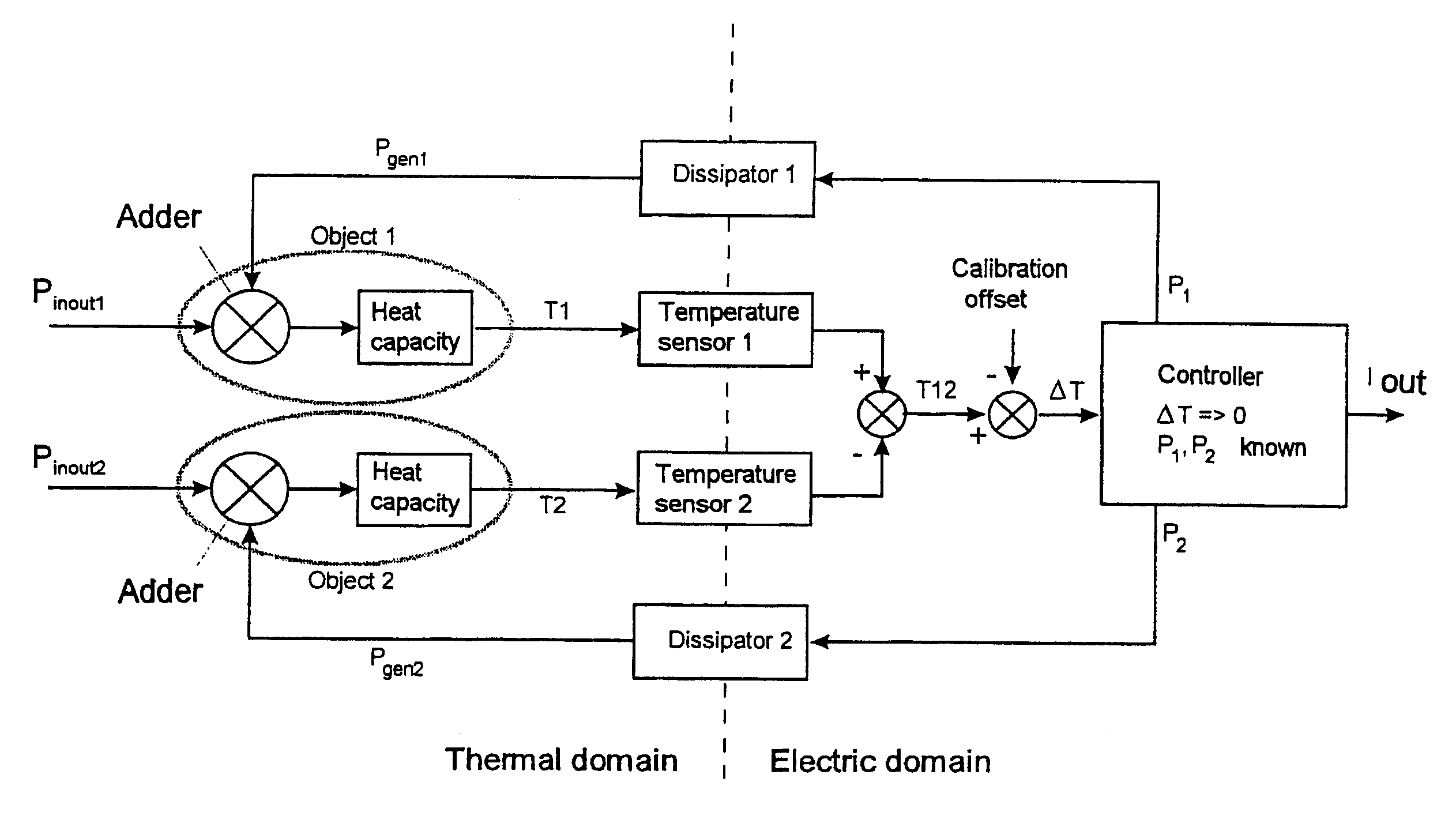
A generic embodiment of the invention is shown in FIG. 24. Here, two temperature-dependent resistances are used as objects. The objects are surrounded by flowing medium. By applying the electric currents I.sub.1,I.sub.2 and measuring the resulting voltages V.sub.1,V.sub.2, the controller knows the powers (P.sub.gen1 =I.sub.1 *V.sub.1) and (P.sub.gen2 =I.sub.2 *V.sub.2) dissipated and generated in the two objects. The controller also knows the temperature of the two objects by simultaneously determining V.sub.1 / I.sub.1 =R.sub.1 and V.sub.2 / I.sub.2 =R.sub.2.

In the controller, there may also be implemented a calibration procedure with the purpose of, during said procedure, halting the contr...


PUM


Abstract

The invention relates to a device for measuring the flow of a medium e.g., a gaseous medium or a fluid medium, which device is based on measuring and affecting the temperature distribution of a medium flowing along, which flow sensor comprises two object, each comprising a heating element and a temperature sensor, the measured temperature difference being kept, by way of a control loop, to the value of zero, the asymmetry of the power supply to the objects in order to comply with the aforesaid criterion, according to which the temperature difference must be zero, being representative of the value to be measured of the medium flow, taking into account parameters associated with the medium, such as its density and specific heat.

Description

The invention presented relates to gas and / or fluid flow measurement techniques making use of thermal effects. Convection plays a role here: a moving medium entrains heat (energy) by way of its own heat capacity.A known sensor, in which use is made of said property, is the anemometer. As a rule, the embodiment of such measuring device consists of one or more objects which are heated by a specific dissipated power and in which the flow affects the resulting temperature of said object. Said resulting temperature is a measure of the flow. Said embodiment and method are referred to as "Constant Power Anemometry" or simply CPA method. Also, said object may be kept at a constant temperature difference with respect to a reference temperature, and it may be measured which power to be dissipated is required for that purpose. Said embodiment and method are referred to as "Constant Temperature Anemometry" or simply CTA method.Apart from this, the measuring devices based on thermal effects may ...

Claims


Application Information

Patent Timeline
Patent Type & Authority Patents(United States)
IPC IPC(8): G01F1/699G01F1/696G01P5/10G01F1/68
CPCG01F1/699
Inventor LAMMERINK, THEODORUS SIMON JOSEPH
Owner BERKIN
Why Eureka
Try Eureka