Scalable and modular heat sink-heat pipe cooling system

a heat sink and cooling system technology, applied in the field of heat sinks, can solve the problems of substantial differential temperature, hotter center of integrated circuits having a high power dissipation per unit area, and substantial limitation of thermal contact between heat sinks and integrated circuits

Inactive Publication Date: 2002-04-23
SUN MICROSYSTEMS INC
View PDF33 Cites 46 Cited by
  • Summary
  • Abstract
  • Description
  • Claims
  • Application Information

AI Technical Summary

Problems solved by technology

In such circumstances, the thermal contact between the integrated circuit and the heat sink can be substantially limited, as the actual area of contact between the integrated circuit and the heat sink can be only a small fraction of a potential area for such contact.
In the foregoing type of heat sinks, even with very good thermal coupling between the integrated circuit and the heat sink, there frequently is a substantial differential temperature between the integrated circuit and the cooling fins or protrusions on the heat sink, particularly in the larger integrated circuits having a high power dissipation per unit area.
Further, integrated circuits having a high power dissipation per unit area tend to run hotter in the center of the integrated circuit than at the edges of the integrated circuit because of the lateral flow of heat away from the edges of the silicon chip.
This temperature difference across the chip is undesirable, as even identical transistors operating at different temperatures have different characteristics.

Method used


Image

  • Scalable and modular heat sink-heat pipe cooling system
  • Scalable and modular heat sink-heat pipe cooling system
  • Scalable and modular heat sink-heat pipe cooling system

Examples


Embodiment Construction

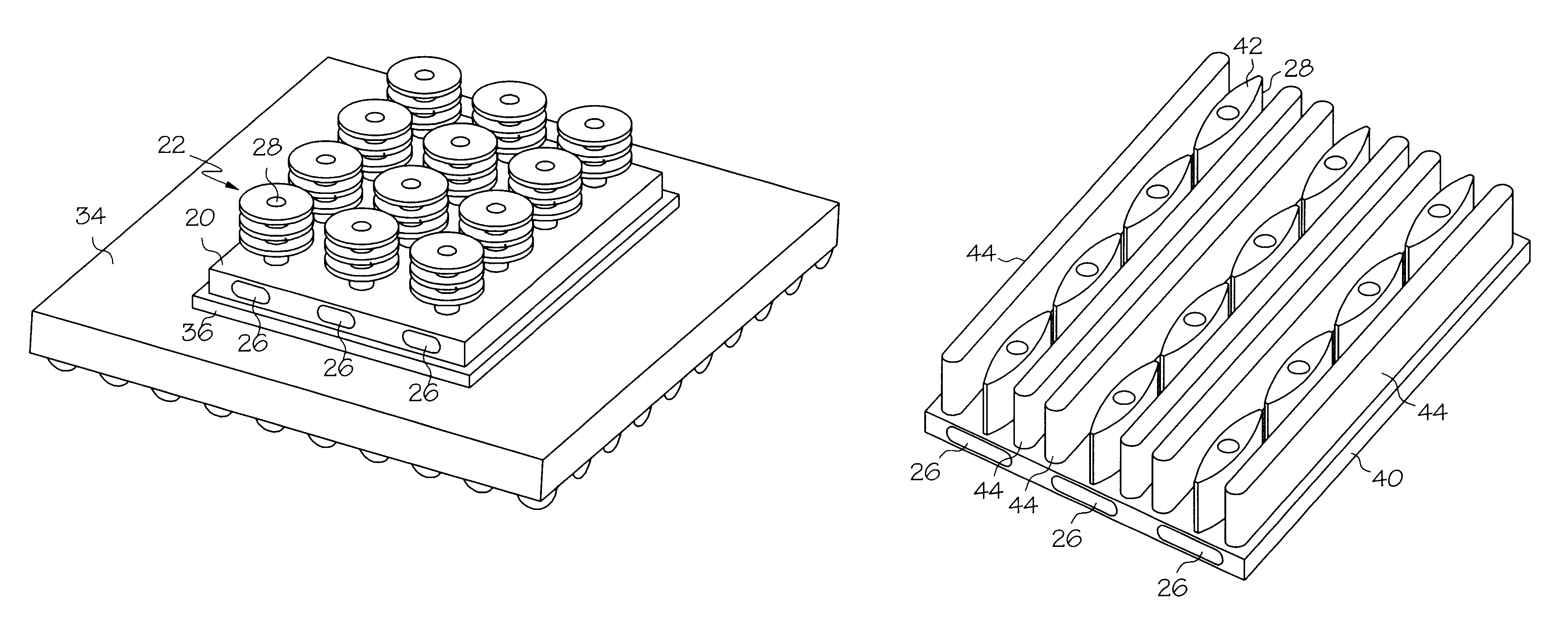
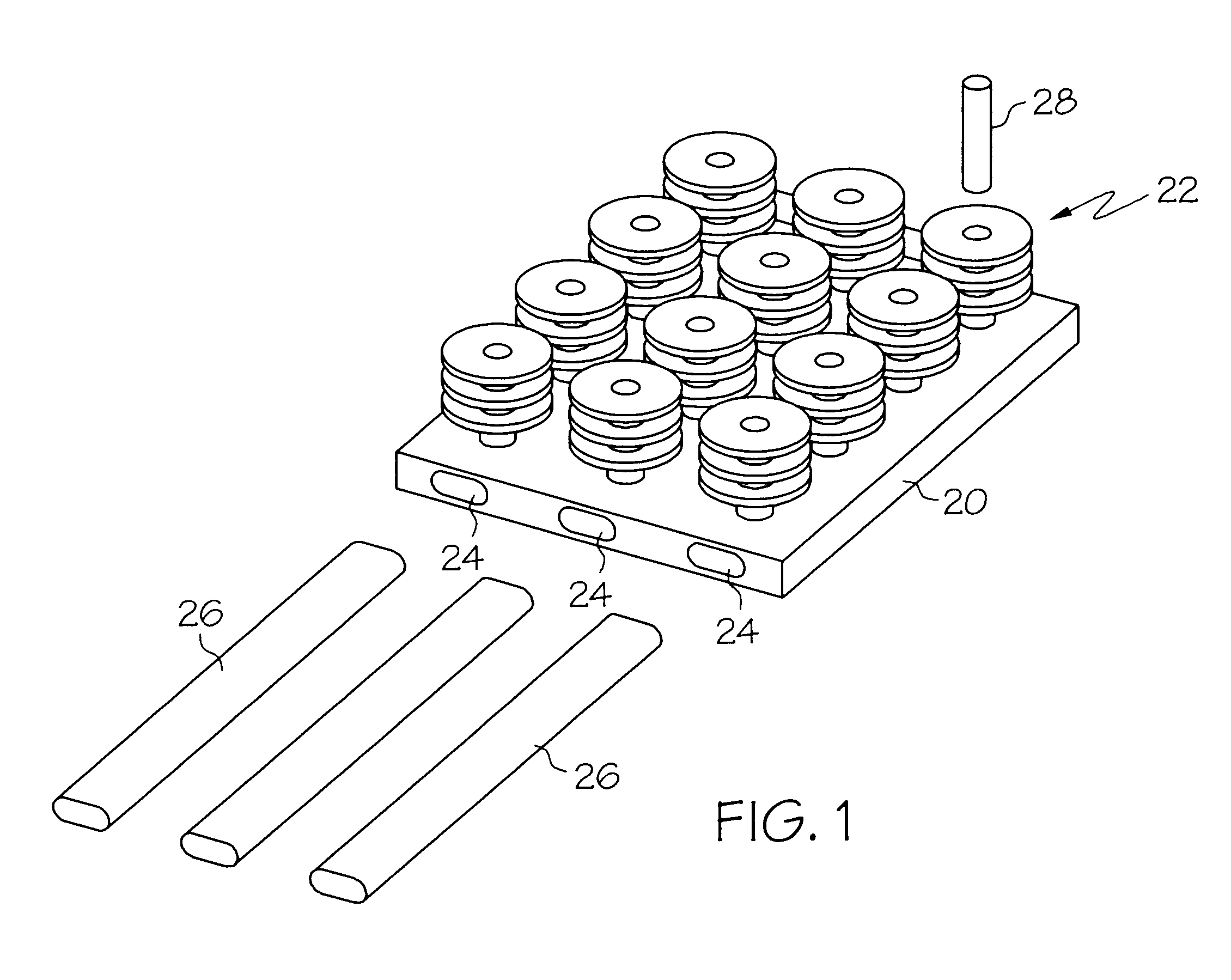
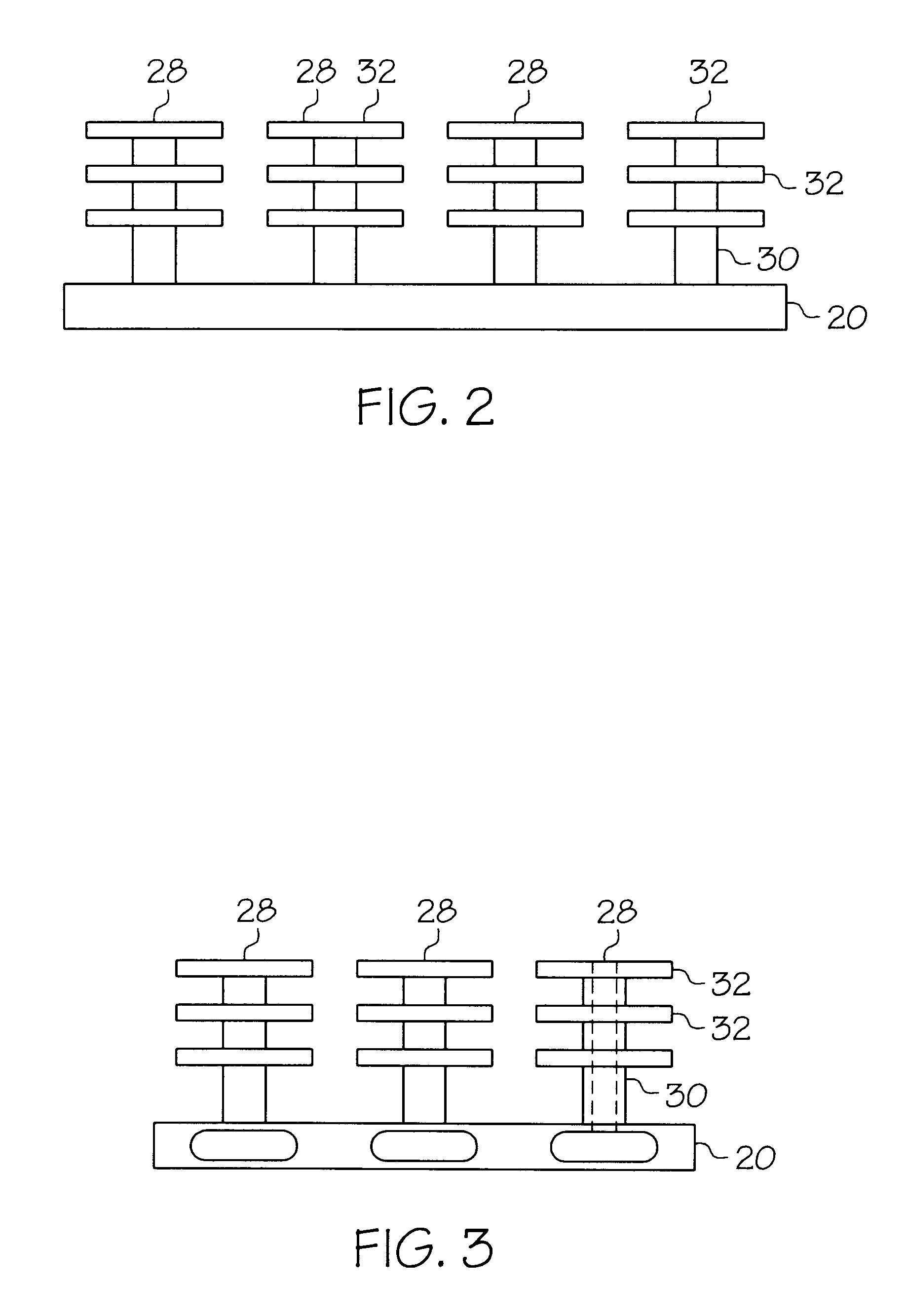
First referring to FIG. 1, an exploded, perspective view of a first embodiment of the present invention may be seen. The heat sink shown therein is comprised of a substantially planar base member 20 and a plurality of finned, tower-like members, generally indicated by the numeral 22, extending upward therefrom. The base 20 is a plurality of longitudinal openings 24 running lengthwise through the base member within which heat pipes 26 are embedded by any of various methods, such as by an appropriate adhesive such as an epoxy adhesive, by cold or hot pressing, or by welding. Also located within an internal diameter of each of the tower-like protrusions 22 is a small cylindrical heat pipe 28, also preferably secured in position with an appropriate adhesive. The heat pipes in the base and in the tower-like protrusions are elongate heat pipes, with the heat pipes in the tower-like protrusions being substantially perpendicular to the heat pipes in the base.

Side, end and top views of the a...


PUM


Abstract

Modular heat sinks utilizing heat pipes to provide a more uniform temperature distribution over a packaged integrated circuit and efficient heat sinking in either free or forced convection environments. The heat sinks utilize both horizontal and vertical heat pipes to transfer heat both horizontally and vertically in the heat sinks. Selection of the number of heat pipes used allows tailoring of the heat sink capabilities for different applications using the same fundamental assemblage of parts. Various embodiments are disclosed.

Description

1. Field of the InventionThe present invention relates to the field of heat sinks for semiconductor devices and integrated circuits.2. Prior ArtVarious configurations of heat sinks for semiconductor devices and integrated circuits are well known in the prior art. One common type of heat sink for mounting on the integrated circuit or other semiconductor device comprises a heat sink having projecting fins or legs to increase the surface area of the heat sink for heat dissipation to the surrounding area, either through free convection or forced convection (fan driven) cooling.In some cases, heat sinks have been configured to somehow snap onto the integrated circuit or other semiconductor device. In such circumstances, the thermal contact between the integrated circuit and the heat sink can be substantially limited, as the actual area of contact between the integrated circuit and the heat sink can be only a small fraction of a potential area for such contact. In such cases, the heat tra...

Claims


Application Information

Patent Timeline
Patent Type & Authority Patents(United States)
IPC IPC(8): H01L23/367H01L23/34H01L23/427H01L23/467
CPCH01L23/367H01L23/427H01L23/467F28D15/0233F28F3/02H01L2924/0002H01L2924/00F28D15/0275
Inventor TANTOUSH, MOHAMMAD A.
Owner SUN MICROSYSTEMS INC
Why Eureka
Try Eureka