Structure of wire winding box

Inactive Publication Date: 2002-04-30
LIAO SHENG HSIN
View PDF5 Cites 38 Cited by
  • Summary
  • Abstract
  • Description
  • Claims
  • Application Information

AI Technical Summary

Problems solved by technology

However, because the conductive devices comprises a large number of small conductive elements such as the conductive rings, the conductive resilient plates, or the steel beads, the assembly process will be time-consuming and laborsome.
Especially, bad contact may easily arise from vibration or abrasion so that long term use can not be achieved.
Besides, due to improper in

Method used


Image

  • Structure of wire winding box
  • Structure of wire winding box
  • Structure of wire winding box

Examples


Embodiment Construction

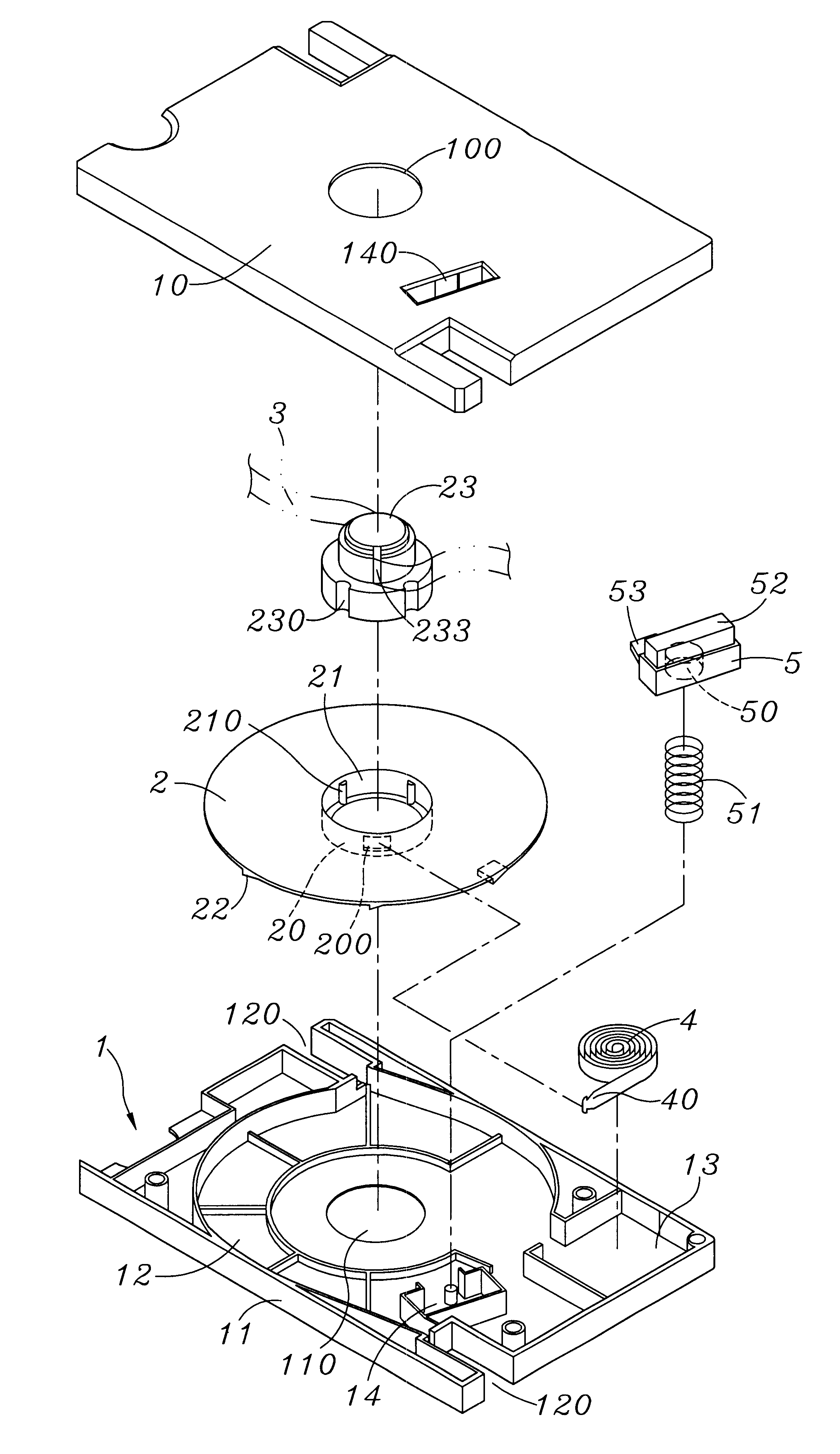
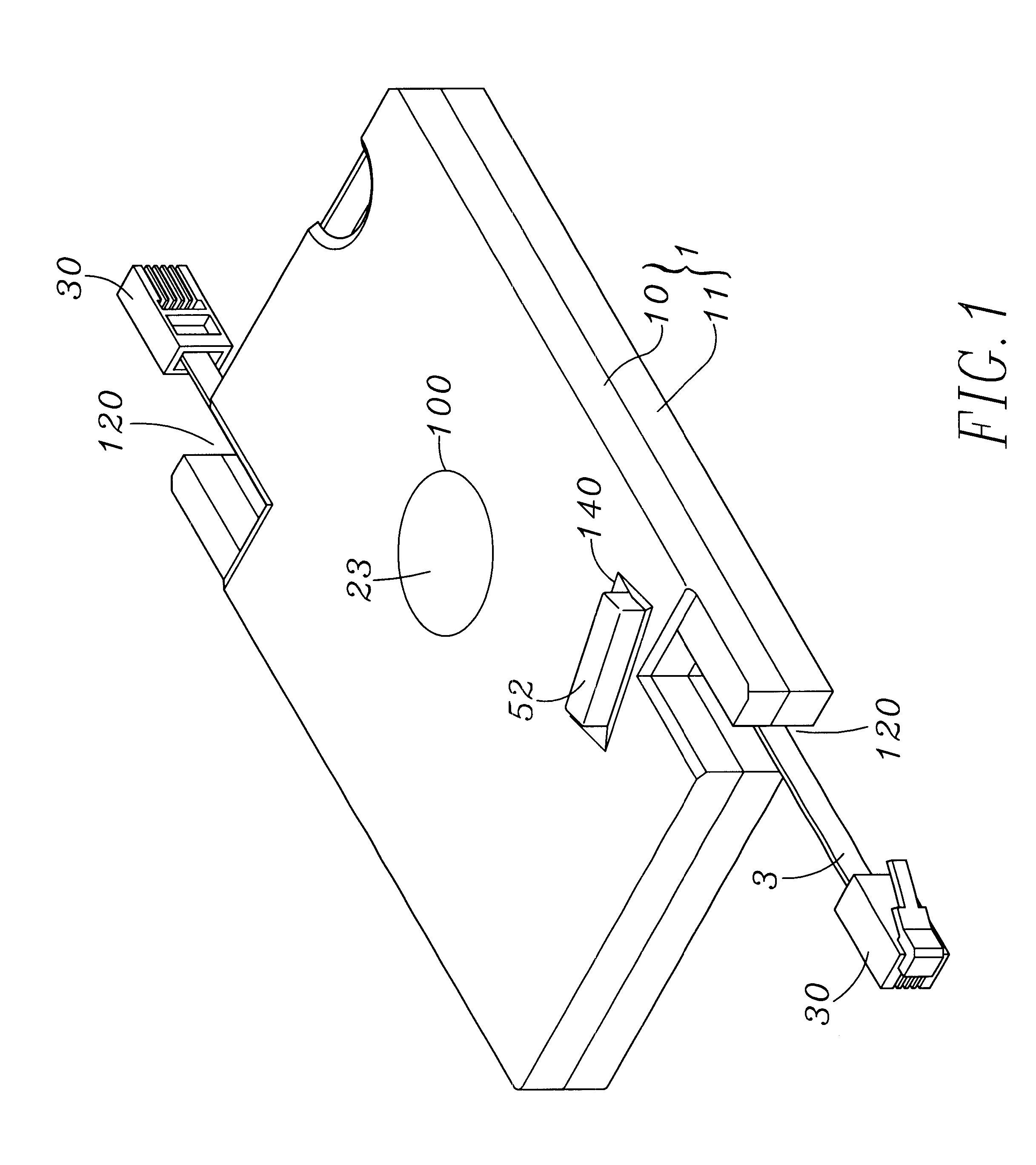
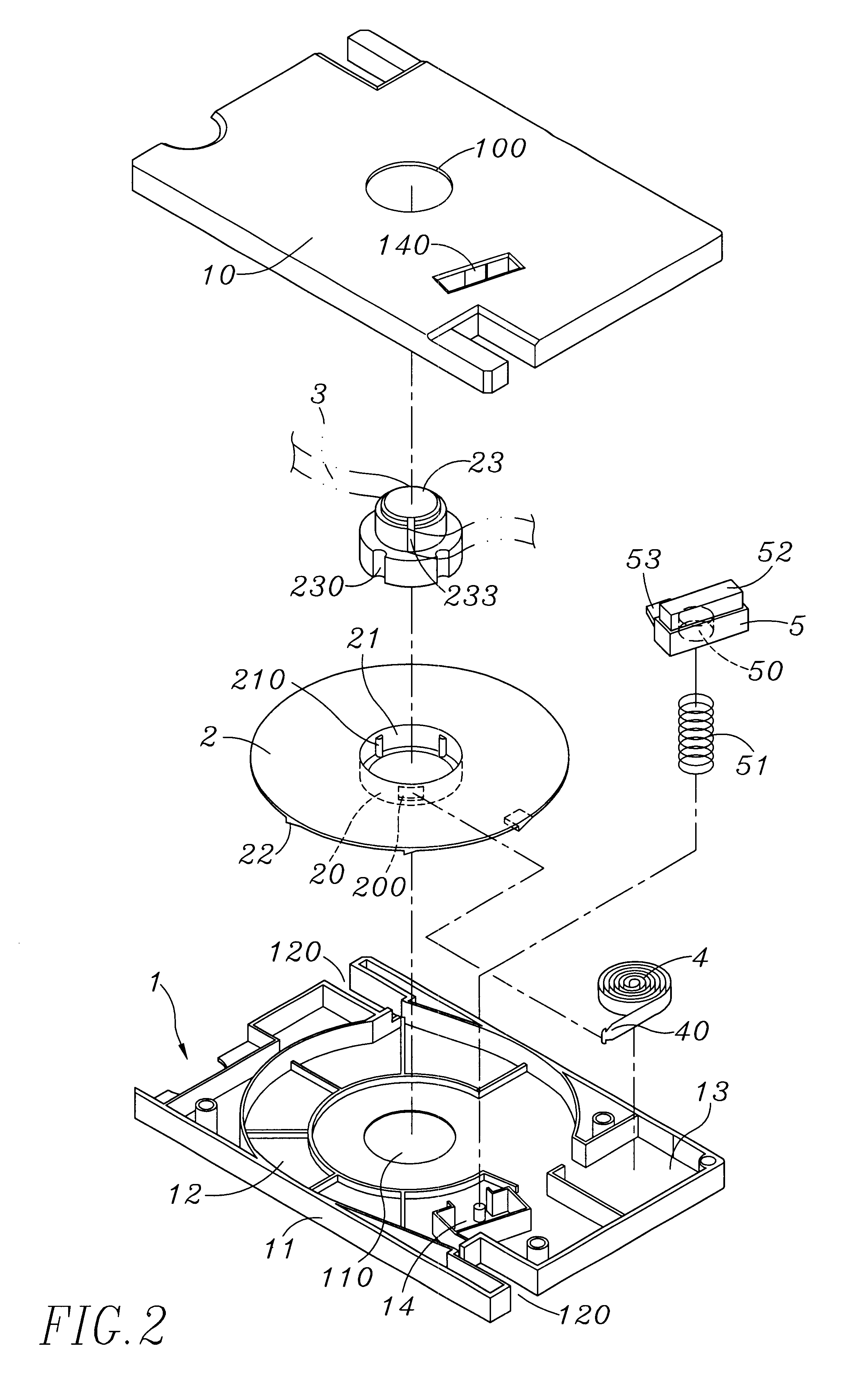
As shown in FIGS. 1 and 2, a wire winding box of the present invention comprises a housing 1, a rotary disk 2, a communication cable 3, a spiral spring 4, and a locking button 5.

The housing 1 comprises a top cap 10 and a bottom cap 11 to form a rotary disk tank 12, a receiving tank 13, a fixing tank 14 having a through hole 140, and two cable outlets 120 connected to the rotary disk tank 12. Pivotal holes 100 and 110 are disposed at the corresponding centers of the top cap 10 and the bottom cap 11, respectively.

The rotary disk 2 is rotatably received in the rotary disk tank 12. A ring 20 having a hook groove 200 and a circular groove 21 having at least a positioning bar 210 at the groove wall thereof are installed at the center of the rotary disk. A shaft bushing having the same number of positioning grooves as that of the positioning bars installed around the periphery thereof can thus be sheathed and positioned in the circular groove 21. As shown in FIGS. 3A to 3C, the bottom of t...


PUM

PropertyMeasurementUnit
Lengthaaaaaaaaaa
Forceaaaaaaaaaa
Structureaaaaaaaaaa

Abstract

The present invention proposes an improved structure of a wire winding box, which comprises a housing, a rotary disk, a communication cable, a spiral spring, and a locking button. The housing comprises a top cap and a bottom cap. The rotary disk is pivotally installed in a rotary disk tank in the housing. A shaft bushing is installed or integrally formed on one disk surface of the rotary disk for the penetrating and winding of the communication cable. A ring is installed on another disk surface of the rotary disk to be hooked by the spiral spring received in a receiving tank beside the rotary disk tank to provide uniform rewinding force for the rotary disk with respect to the communication cable. The locking button is worked by a resilient element to let a push part thereof protrude out of the housing. A bump is formed on the locking button and extends to the rotation path of a slanting retaining block preset on the rotary disk to stop the retaining block timely to lock the rotary disk. Easier production and assembly of the wire winding box can thus be achieved. More convenient use can also be attained.

Description

The present invention relates to a wire winding box and, more particularly, to a miniature wire winding box, which can be used in wired-communication apparatuses to provide free pull-out of a communication cable with a proper length, and can rewind the cable automatically to avoid the improper winding of the cable. Moreover, the present invention has a simpler structure.When using communication apparatuses such as computers, modems, telephones, or facsimile machines, communication cables with proper lengths are needed to achieve electric connection. To prevent excess communication cables from improper winding or too short communication cables from not meeting practical requirements, wire winding boxes have been used. Most wire winding boxes comprise mainly a shell, a rotary disk, a spiral spring, and a communication cable. The spiral spring is fixedly connected to the rotary disk so that the communication cable wound around the rotary disk can be rewound because of the resilient pot...

Claims


Application Information

Patent Timeline
IPC IPC(8): B65H75/38B65H75/04B65H75/48B65H75/44B65H75/14B65H75/40H02G11/02H02G11/00H04M1/15
CPCB65H75/14B65H75/4431H04M1/15H02G11/02B65H2701/515B65H2701/5122
Inventor LIAO, SHENG HSIN
Owner LIAO SHENG HSIN
Why Eureka
Try Eureka