
Method of introducing heavy article and method of discharging heavy article

a technology of heavy articles and discharging methods, which is applied in the directions of refusing gathering, transportation and packaging, rigid containers, etc., can solve the problems of large volume of storage space for temporary storage of transported cargoes, inability to introduce coils deeply into dry containers, and inability to introduce outside moisture into containers

Inactive Publication Date: 2002-04-30
TOYOTA STEEL CENT CO LTD
View PDF16 Cites 36 Cited by
  • Summary
  • Abstract
  • Description
  • Claims
  • Application Information

AI Technical Summary

Benefits of technology

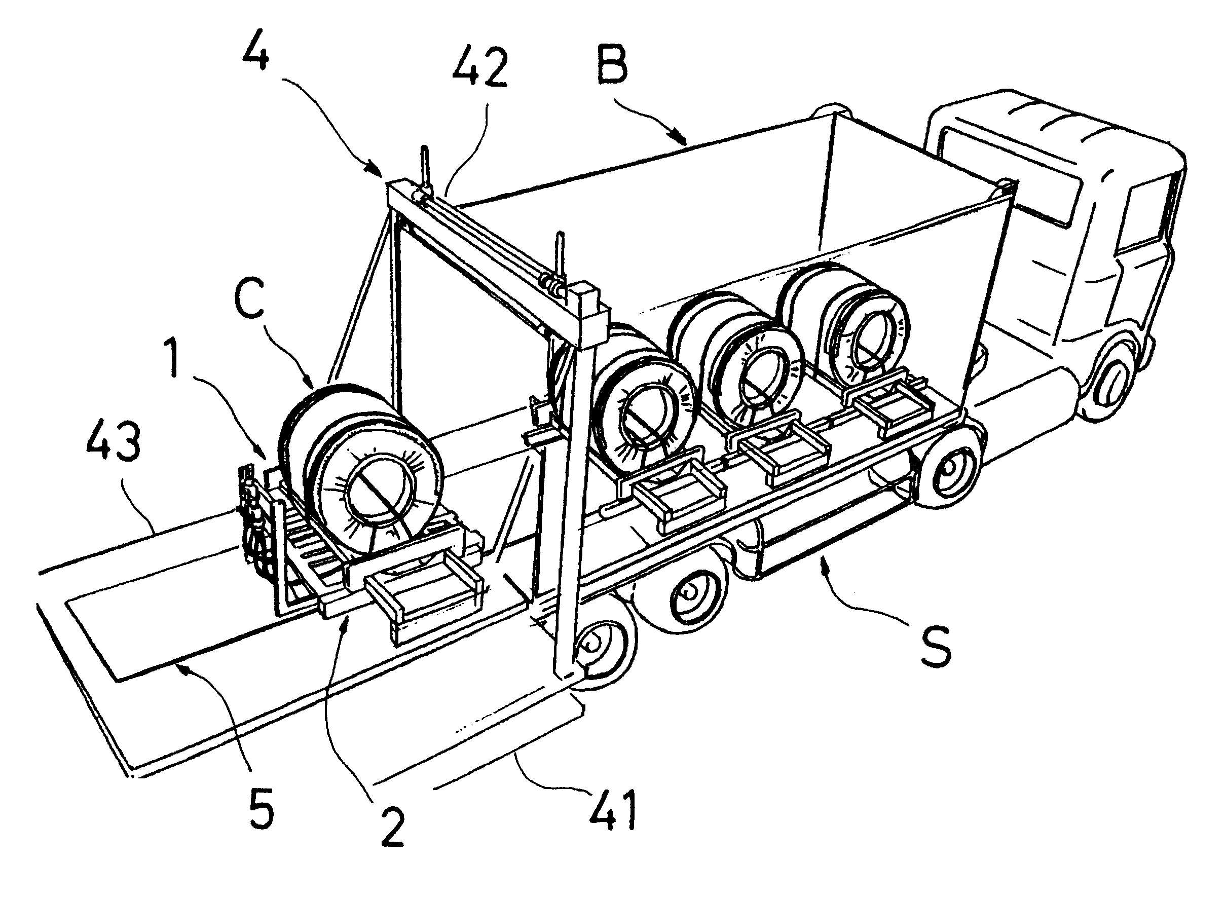
In view of the foregoing, another object of the present invention is to provide a heavy-article carrying vehicle which enables a heavy article to be transported with a container and which is able to easily introduce a heavy article into a container without damaging the floor of the container.

Problems solved by technology

Therefore, a vast space is required to temporarily store the transported cargoes in a large quantity.
Since the dry container has an opening in the side surface thereof, the crane or the like for suspending and moving the cargo cannot introduce the coil into the dry container.
Therefore the coil cannot be introduced deeply into the dry container.
Since the above-mentioned containers have poor air tightness, outside moisture is undesirably introduced into the container.
Moreover, the costs of the foregoing containers are higher than those of the dry containers.
Since the foregoing containers do not exist in a sufficient number, the containers cannot easily be reserved.
Moreover, the open-top containers usually encounter difficulty in opening the ceilings thereof as compared with the dry containers.
Even if the dry containers are employed, use of packing materials, such as wood, which easily contain water causes water in the packing material to be vaporized.
Therefore, rust is easily formed.
The foregoing operation requires great labor and excessively long time.
As a result, introduction of the heavy article by using the carrying vehicle, such as the forklift, which runs on the surface of the floor, cannot easily be performed.
Therefore, the minimum road clearance and the diameters of the wheels cannot be enlarged.
The limitation of the size of the carrying vehicle may cause another problem of limiting the weight of the heavy article which can be introduced by the carrying vehicle.
In such a case, there is the possibility that the bottom surface of the carrying vehicle is brought into contact with the floor.
The close packing operation demands considerable labor and time.
However, the coil sometimes suffers from the flaw during loading or unloading the coil.
Since the coils are directly stacked during shipping, there arises another problem of deforming the coil owning to the weights of the stacked coils.
Since no container is used, a usual periodical shipping service cannot be used.
Therefore, a period of time required to complete the transportation is elongated undesirably.
On the other hand, the open-top container and the flat-track container having opened upper portion cannot maintain air tightness.
Therefore, packing of the coil for preventing rust cannot be simplified.
Thus, the problem of packing cannot be solved.
Since the open-top container and the flat-track container are costly containers and, therefore, only a small quantity is distributed.
Therefore, there arises another problem in that the cost cannot be reduced and smooth physical distribution cannot be performed.
Therefore, when the coil is introduced deeply into the dry container through the openings of the doors, the size of the carrying vehicle, such as the forklift, is limited such that the carrying vehicle can be introduced into the container.
Therefore, the above-mentioned method has a limitation that the weight of a cargo which can be handled must be lighter than a weight which can be lifted by the carrying vehicle which can be introduced into the container.
Since loads are, on the floor, concentrated to a point of contact of each tire of the carrying vehicle, such as the forklift, there arises a problem in that the bottom of the container is broken by the carrying vehicle introduced into the container.
Therefore, there arises another problem in that excessively heavy weight is added to each point of contact.
When employing a conveyance conveyor in place of the forklift, the foregoing problem will occur.
Since the forklift has the counter balance, the excessive weight will be added to the floor of the container.
The foregoing problems have been experienced with not only the thin-plate but also the heavy article like machinery.
Since the leakage-preventive sheet exhibits flexibility, a gap cannot easily be formed between the upper surface of the table and the floor surface of the transporting receptacle differently from a structure using a plate having rigidity to close the gap.
Moreover, a possibility that air supply is interrupted because the unnecessary portion of the air supply hose is stepped on can be lowered.
As a result, it is unlikely to have the floor broken by the weight.
As a result, a stepped portion from the height of the upper surface of the table cannot be generated.
Therefore, bending moment is not allowed to be transmitted to the slide-portion lifting means owning to a load exerted on the engaging members.
Therefore, a complicated or a large apparatus for loading / unloading a cargo is not required to introduce the heavy article by effectively using the carrying vehicle.
As a result, great time and labor cost can be saved.

Method used


Image

  • Method of introducing heavy article and method of discharging heavy article
  • Method of introducing heavy article and method of discharging heavy article
  • Method of introducing heavy article and method of discharging heavy article

Examples


second embodiment

A pallet, a heavy-article carrying vehicle, a heavy-article introducing / discharging stage and a carrying method using the same are as follows.

(1) Pallet

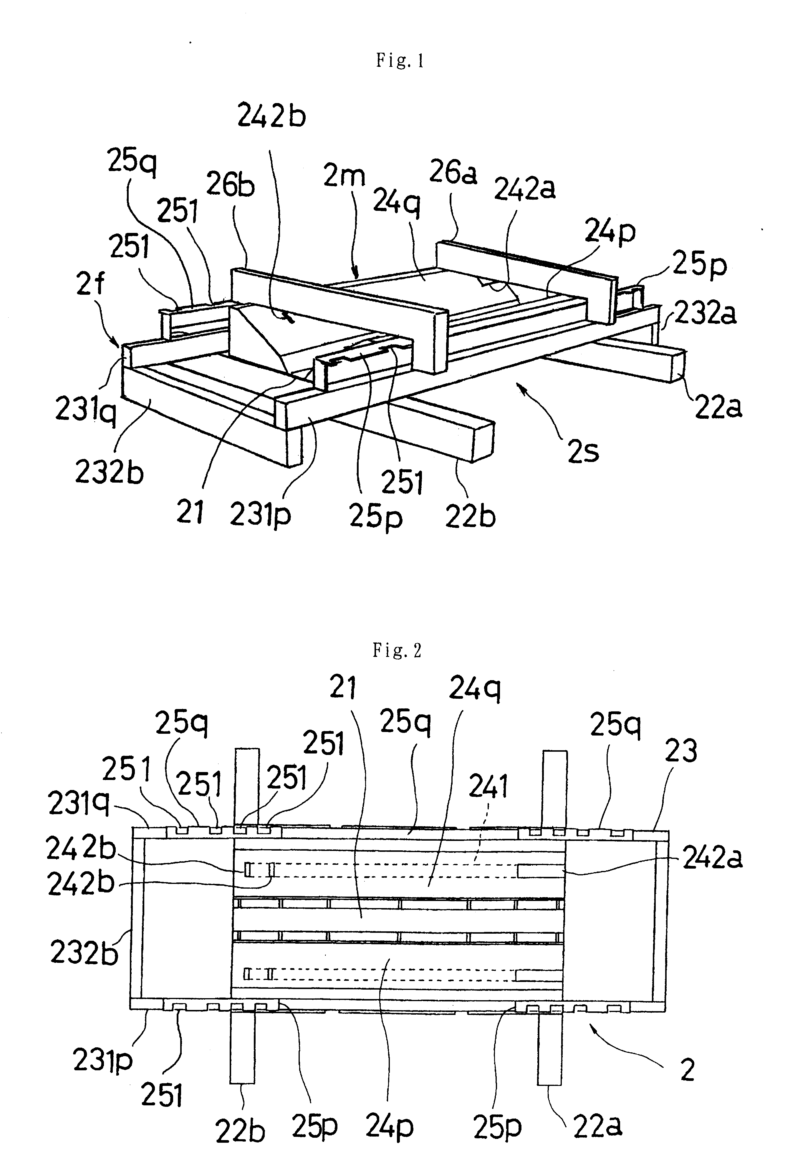
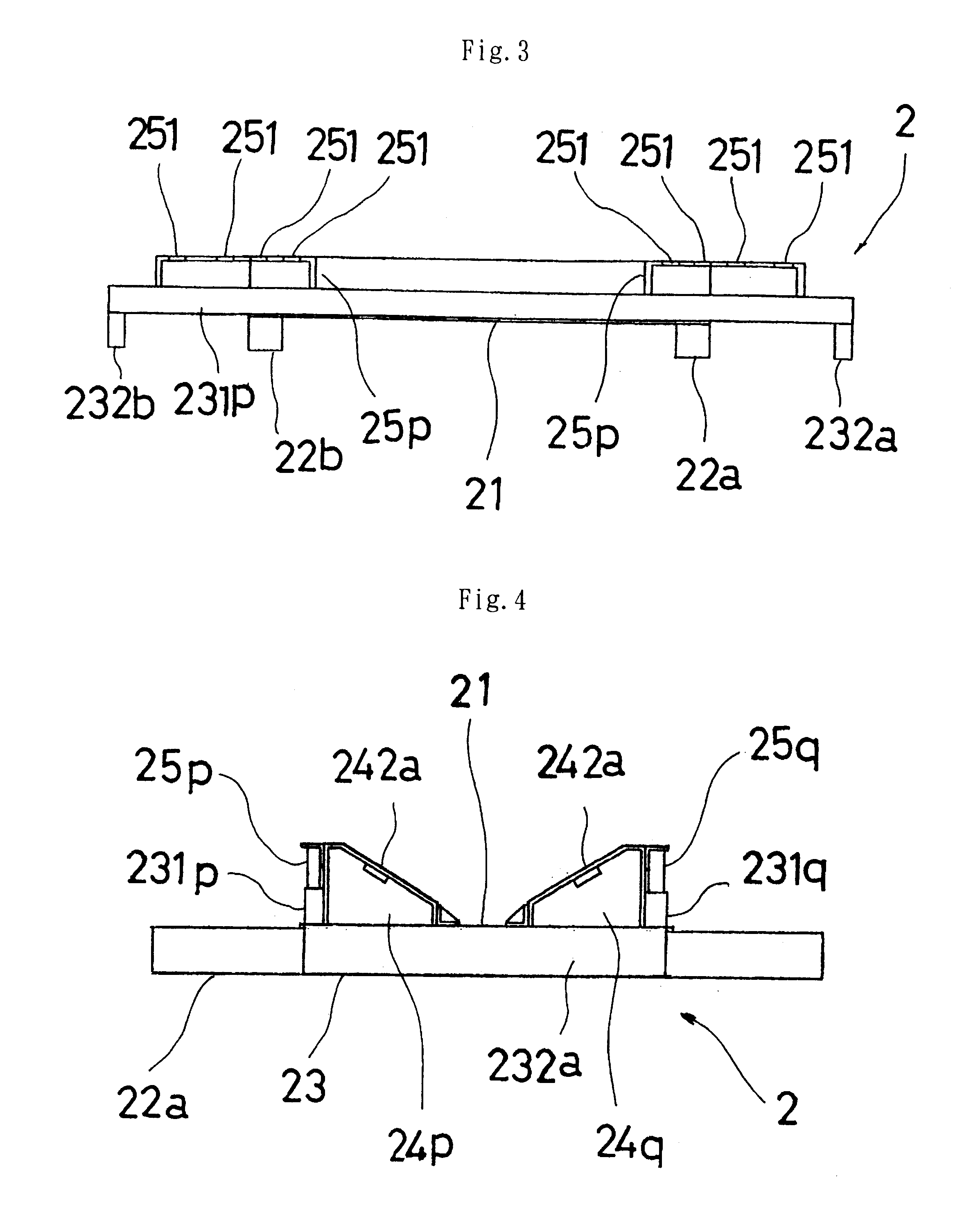
A pallet 2 for a coil-shape heavy article according to this embodiment has a structure similar to that of the pallet according to the first embodiment. The pallet of the second embodiment is different from that of the first embodiment in that the movement inhibiting member and a stack-support portion are further provided.

As shown in FIGS. 36 to 39, the pallet 2 for a coil-shape heavy article according to this embodiment incorporates the sub-arms 231p, 231q which have side-end guides 233a, 233b in place of the sub-leg members 232a, 232b, respectively.

As shown in FIGS. 37 and 38, the side-end guides 233a, 233b are rod members having two ends connected to the leading ends of the sub-arms 231p, 231q and longitudinally disposed. The distance between the outer surfaces of the side-end guides 233a, 233b is shorter than the width of the inte...


PUM


Abstract

A method of introducing / discharging a heavy article is provided that allows for introducing and / or discharging a coil-shape heavy article to and from a transporting receptacle. The method includes utilizing a pallet, a stage, and a carrying vehicle to introduce / discharge the coil-shape heavy article. A coil-shape heavy article is secured to the pallet using a securing member and is transported, while secured to the pallet, between the stage, which is secured to the transporting receptacle, and the transporting receptacle. The stage includes a table having a height that is adjustable relative the floor surface of the transporting receptacle. Movement of the pallet between the stage and the transporting receptacle is performed by levitating a support frame of the carrying vehicle on which the pallet has been positioned using a controllable discharge of gas exiting from exhaust nozzles of the carrying vehicle.

Description

The present invention relates to a pallet for transporting a heavy article like a steel material, contained in a transporting receptacle, such as a container. More particularly, the present invention relates to a pallet for a coil-shape heavy article for transporting a heavy article like a coiled steel plate in a transporting receptacle, for example, a container, that allows the cargo to be easily secured, prevents the cargo from being damaged, and reduces the cost, as well as being suitable to be moved by a carrying vehicle (particularly a levitation-type carrying vehicle).Also the present invention relates to a carrying vehicle, and more particularly, to a carrying vehicle with which a heavy article can easily be introduced into a container without damaging the floor of the container.Moreover, the present invention relates to a stage for introducing / discharging a heavy article to and from a transporting receptacle and a method of introducing / discharging a heavy article. More parti...

Claims


Application Information

Patent Timeline
Patent Type & Authority Patents(United States)
IPC IPC(8): B65D85/66B65D19/44B65D19/38
CPCB65D19/44B65D85/66Y10S414/124
Inventor IWASAKI, NOBUOTSURUTA, KOUICHIAOKI, TATUHIKOITOU, NOBUAKI
Owner TOYOTA STEEL CENT CO LTD
Learn More