Hydrodynamic seal with improved extrusion abrasion and twist resistance

a technology of extrusion abrasion and twist resistance, applied in the direction of engine seals, mechanical devices, engine components, etc., can solve the problems of reduced modulus of seal materials, reduced extrusion resistance, and failure of seals

Inactive Publication Date: 2002-05-07
KALSI ENG
View PDF20 Cites 70 Cited by
  • Summary
  • Abstract
  • Description
  • Claims
  • Application Information

AI Technical Summary

Problems solved by technology

These stresses, and other stresses described below, can result in progressive extrusion damage to dynamic sealing lip 14 which eventually causes seal failure when the damage reaches theoretical intersection 22.
The modulus of the seal material decreases with temperature, which reduces extrusion resistance.
In high pressure sealing applications extrusion can lead to fatigue damage known as "nibbling" or "extrusion damage", which can cause seal material loss and thereby reduce the operational life of the seal.
Extrusion damage is caused by cyclic stressing of the seal material which protrudes into the extrusion gap, which ultimately causes the protruding material to fatigue and break away from the sealing element.
Dynamic fluctuations in the size of the extrusion gap due to lateral shaft motion (and other factors) causes high variations in the radial compression of the extruded material, and the resulting cyclic stress causes extrusion damage which looks as if tiny bites have been "nibbled" out of the environmental side of the seal.
Extrusion related fatigue damage can cause eventual seal failure by several different mechanisms.
In severe cases, the seal fails catastrophically due to gross material loss when the damage reaches theoretical intersection 22.
Nibbling damage can also partially interrupt the hydrodynamic film which may cause the seal to run hotter and suffer from premature compression set and heat--related surface embrittlement.
Although the useful operating pressure range of the present day hydrodynamic rotary shaft seal is unequaled by any other interference type rotary seal, the performance and life are ultimately limited by susceptibility to extrusion and abrasion damage.
Unfortunately, one cannot simply increase the overall durometer hardness of the seal to a very high value to obtain the high modulus needed for increased extrusion resistance because under initial radial compression the high modulus would cause a very high contact pressure at the dynamic sealing interface that would be incompatible with sustained rotary operation due to a high resulting level of self-generated heat.
The contact pressure at the dynamic sealing interface is a related to the percentage of compression and the modulus of elasticity of the seal material, therefore the choice of modulus is limited by the required percentage of initial compression and by the maximum practical interfacial contact pressure.
The small extrusion gap clearance required for high pressure operation with present day hydrodynamic seals is difficult to implement unless special mechanical contrivance such as the force--balanced laterally translatable seal carrier of U.S. Pat. No. 5,195,754 is used.
Deflection and lateral articulation within bearing clearances due to side load often exceed the required seal to housing extrusion gap, and the resulting rotary metal to metal contact between the relatively rotatable surface 30 and the housing 28 damages both and generates frictional heat than can melt the seal and cause failure.
Such twisting can subject the seal to skew within the gland, disposing the seal to skew induced wear resulting from environmental impingement on skewed portions of the seal.
As a result, seal life is shortened when such counter--clockwise twisting occurs.
This situation can result in rather quick wear of dynamic sealing surface 16 as the axial motion drugs abrasives across the entire minimum dimension 24.

Method used


Image

  • Hydrodynamic seal with improved extrusion abrasion and twist resistance
  • Hydrodynamic seal with improved extrusion abrasion and twist resistance
  • Hydrodynamic seal with improved extrusion abrasion and twist resistance

Examples


Embodiment Construction

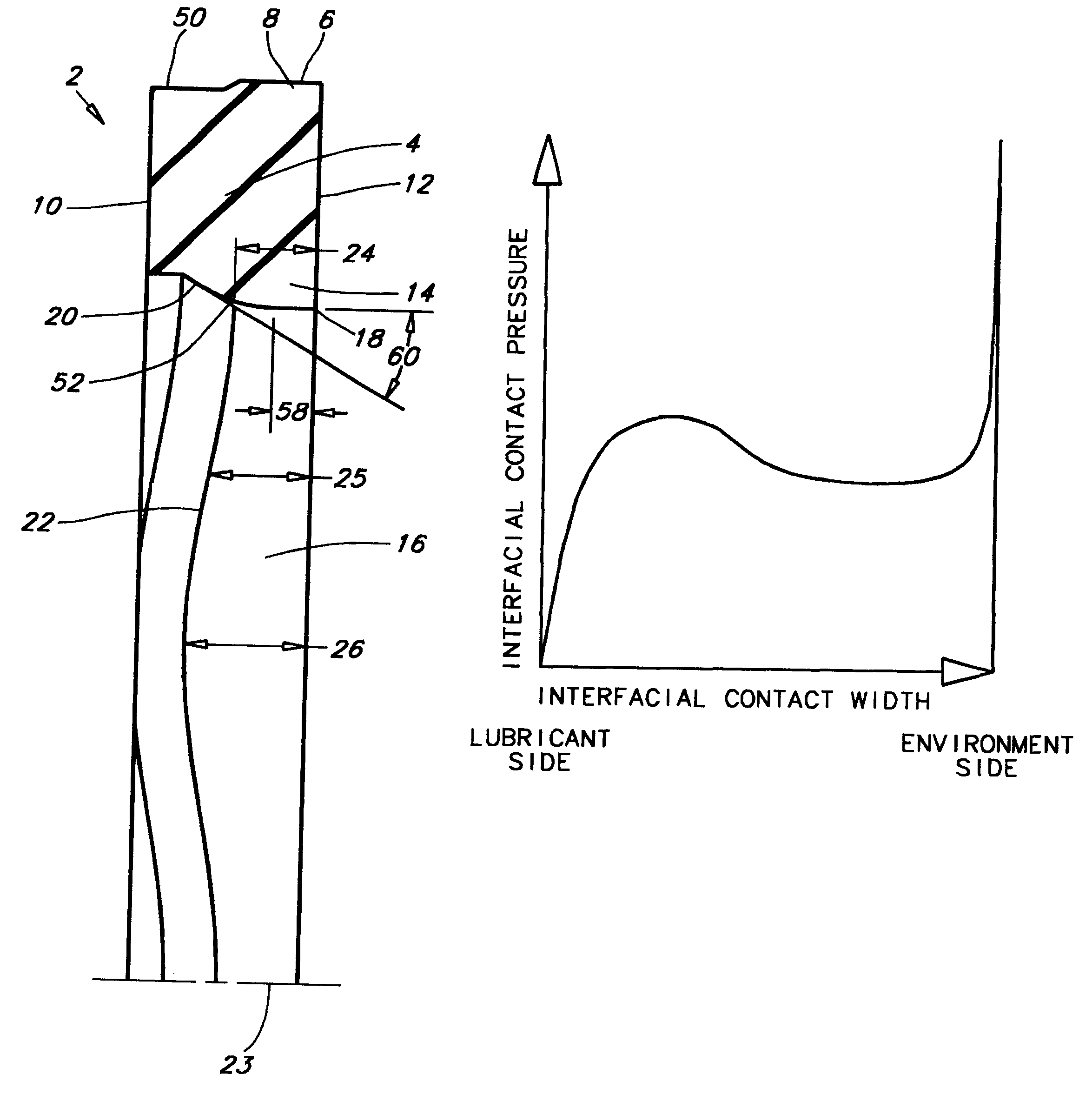
The present invention is a hydrodynamically lubricated compression--type rotary seal that is suitable for lubricant retention and environmental exclusion. It has been engineered such that it's geometry, interfacial contact pressure, and response to relative rotary motion combine to generate a hydrodynamic lubricant film which separates the seal from the mating relatively rotatable surface, and combine the exclude contaminants, and thereby promote long sealing life. The thickness of the film is proportional to the interfacial contact pressure and also dependent on other factors, such as the installed shape of the hydrodynamic geometry and the viscosity of the lubricant. The seals of the present invention are bi-directional; that is to say they achieve efficient hydrodynamic lubrication in response to either clockwise or counter-clockwise relative rotation.

The invention is directed at prolonging seal life in applications where the lubricant pressure may be significantly higher than th...


PUM


Abstract

A hydrodynamically lubricating seal has a generally circular seal body defining a static sealing surface and having a dynamic sealing lip projecting from the seal body and defining a dynamic sealing surface, a non-hydrodynamic edge and a non-circular angulated flank having a flank angle. The flank angle and the dynamic sealing surface have theoretical intersection being positioned from the non-hydrodynamic edge by a variable distance having a minimum dimension being greater than {fraction (1/16)} inch and also having a maximum dimension. The circular seal body defines a theoretical center-line and, when viewed in a longitudinal cross-section taken along the theoretical center-line, a hydrodynamic inlet curve is shown that blends the theoretical intersection between the flank angle and the dynamic sealing surface. This hydrodynamic inlet curve is tangent to the dynamic sealing surface at a location of tangency and has a rate of curvature less than the rate of curvature of a ⅛ inch radius.

Description

1. Field of the InventionThe present invention relates generally to hydrodynamically lubricating seals having a hydrodynamic geometry which interacts with lubricant during rotation of a relatively rotatable surface to wedge a film of lubricant into the interface between the seal and the relatively rotatable surface to thereby provide for cooling and wear resistance of the seal and to significantly extend the service life thereof. More specifically, the present invention concerns the provision of a dynamic sealing lip geometry in a hydrodynamic seal which enhances lubricant retention and environmental exclusion of the seal and maintains interfacial contact pressure within the dynamic sealing interface for efficient hydrodynamic lubrication.2. Description of the Prior ArtThe prior-art hydrodynamically lubricated compression--type rotary shaft seals disclosed in U.S. Pat. No. 4,610,319, 5,230,520, 5,678,829, 5,738,358, 5,873,576 and 6,036,192 are known in the industry by the registered...

Claims


Application Information

Patent Timeline
Patent Type & Authority Patents(United States)
IPC IPC(8): F16J15/16F16J15/32
CPCF16J15/162F16J15/3244F16J15/166F16J15/164
Inventor DIETLE, LANNIE L.KALSI, MANMOHAN S.
Owner KALSI ENG
Why Eureka
Try Eureka