Disk array control device with two different internal connection systems

Inactive Publication Date: 2002-05-07
HITACHI LTD
View PDF5 Cites 95 Cited by
  • Summary
  • Abstract
  • Description
  • Claims
  • Application Information

AI Technical Summary

Problems solved by technology

However, with the disk array controller of the shared bus connection form shown in FIG. 3, because it is impossible to change or modify the transfer ability of the once-mounted shared bus in accordance with the add-in provision of the channel IF units and disk IF units, it remains difficult to flexibly accommodate such add-in extended reconfiguration of the channel IF units and disk IF units.
With the shared bus connection form shown in FIG. 3, in the case of employing high-performance processors as the microprocessors provided in the channel IF units and those in the disk IF units, the shared bus's transfer ability becomes a bottle neck when compared to the performance of these processors, which

Method used


Image

  • Disk array control device with two different internal connection systems
  • Disk array control device with two different internal connection systems
  • Disk array control device with two different internal connection systems

Examples


embodiment 1

[Embodiment 1]

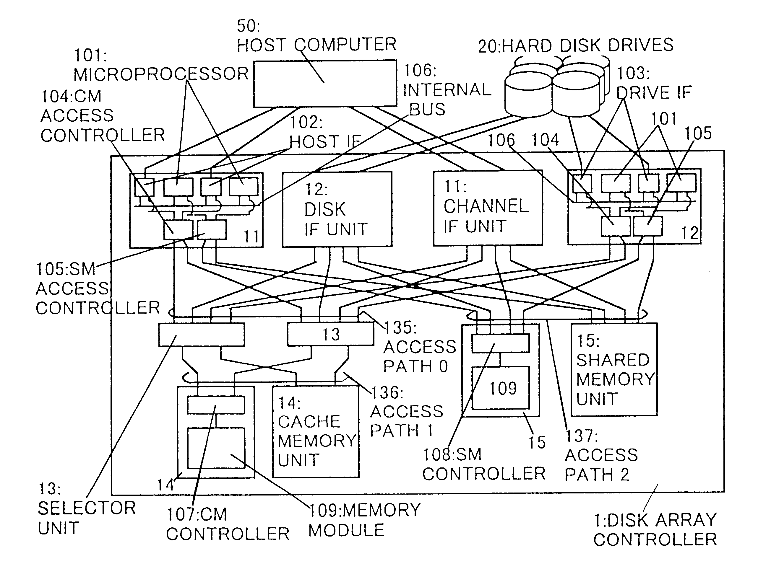
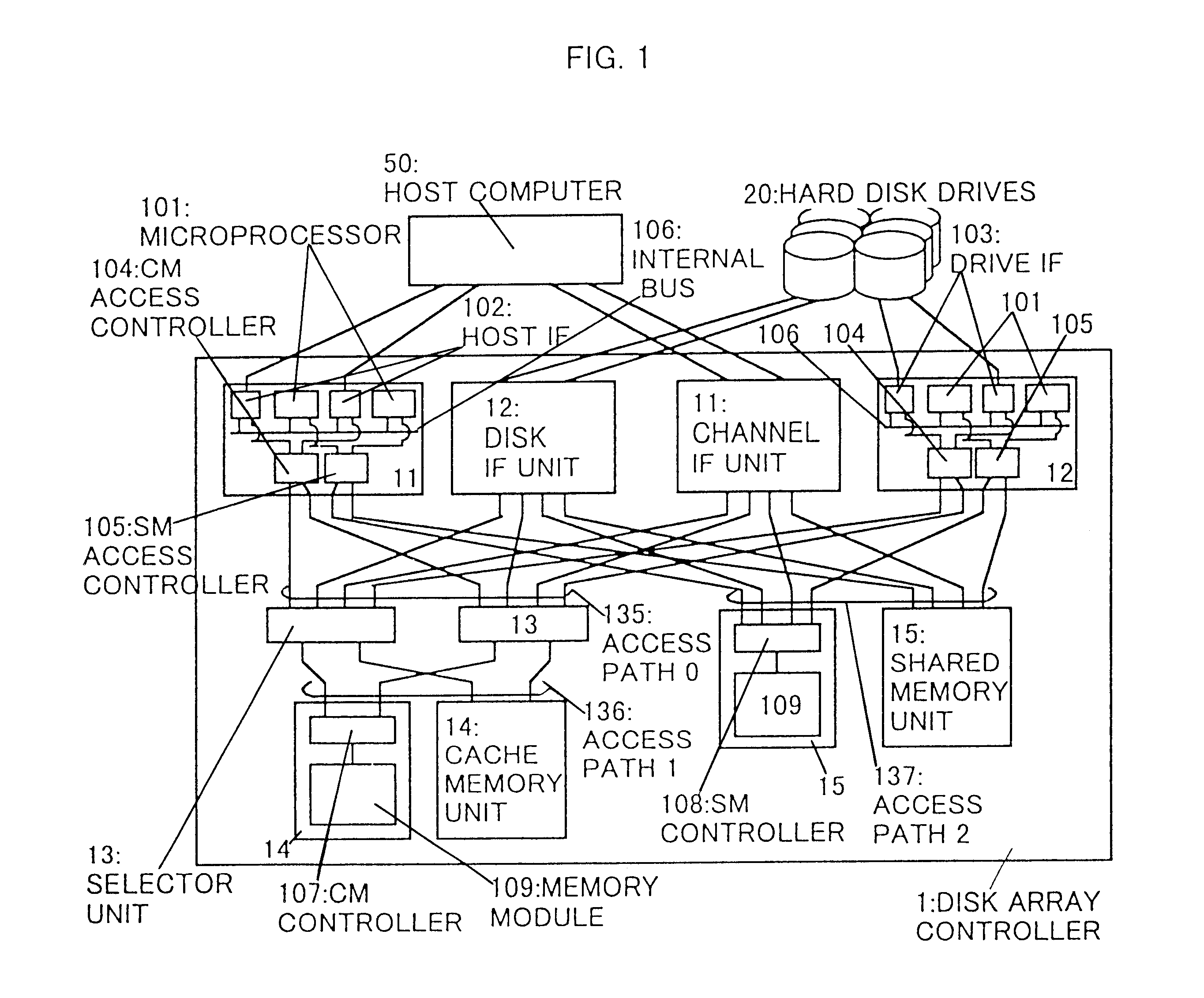
Referring now to FIG. 1, there is shown one embodiment of this invention.

A disk array control device 1 is arranged including two channel interface (IF) units 11 operatively associated with a host computer 50, two disk IF units 12 associated with a magnetic disk device 20 that has a group of multiple hard disk drives (HDDs), two selector units 13, two cache memory units 14, two common-use or "shared" memory units 15, an access path 0:135, an access path 1:136, and an access path 2:137.

The channel IF unit 11 has two host IFs 102 associated with the host computer 50, two microprocessors 101 for control of input / output with respect to the host computer 50, a cache memory (CM) access control unit 104 for controlling access to the cache memory units 14, and a shared memory (SM) access control unit 105 for controlling access to the shared memory units 15, and executes data transmission between the host computer 50 and the cache memory units 14 along with transmission of contr...

embodiment 2

[Embodiment 2]

In FIG. 1, it becomes possible to increase the reliability of data by duplicating all or part of the memory region between two cache memory units 14 to permit writing of the same data into such duplicated two regions when writing data into the cache memory units 14.

A procedure of writing data into two cache memory units 14 duplicated is as follows.

The host IF 102 or the drive IF 103 that has received an instruction to start access sends forth via control lines 1:211 a signal indicative of the access start toward the data transfer control unit 310 within the CM access control unit 104. Simultaneously, transmit two addresses and commands along with a single datum through data lines 210.

The CM access control unit 104 stores in its packet buffer(s) 303 the two addresses and commands and single datum that have been sent via the data line(s) 210. The data transfer control unit 310 performs arbitration to determine the use right of the path IFs 301 for switching the selector ...

embodiment 3

[Embodiment 3]

With the disk array controller 1, in case a plurality of cache memory units 14 are provided, there should be required a function of copying data from a certain cache memory unit 14 to another cache memory unit 14. This function is achievable by a procedure as will be described below.

The host IF 102 or the drive IF 103 that has received the instruction to start getting access sends out via control lines 1:211 a signal indicative of the access start to the data transfer control unit 310 in the CM access control unit 104. Simultaneously, transmit two addresses and commands through data lines 210. One address and command of the two may be an address of the copy source and a read command whereas another address and command might be an address of a copy destination or target and a write command. Here, an explanation will be given under an assumption that the CM controllers a:107 is the copy source whereas the CM controller b:107 is the target.

The CM access control unit 104 s...


PUM


Abstract

A disk array control device which includes a plurality of channel interface (IF) units, a plurality of disk IF units, a cache memory unit, and a shared memory unit. The connection system between the plurality of channel IF units and plurality of disk IF units and the cache memory unit is different from the connection system between the plurality of channel IF units and plurality of disk IF units and the shared memory unit. In the invention the plurality of channel IF units and the plurality of disk IF units are connected via a selector to the cache memory unit, whereas the plurality of channel IF units and the plurality of disk IF units are directly connected to the shared memory unit with no selectors.

Description

1. Field of the InventionThe present invention relates to control devices of disk array devices for storing data in a plurality of magnetic disk devices.2. Description of the Related ArtIn view of the fact that the input / output (I / O) performance or throughput of a disk subsystem (referred to as "subsystem" hereinafter) is less by approximately three to four orders of magnitude than the I / O throughput of main memories of computers with semiconductor memory devices as their storage media, attempts have conventionally been made to reduce this difference. Namely, attempts have been made to improve the I / O throughput of the subsystem. One prior known approach to improving the subsystem's I / O throughput is to use a system, called "disk array," for constituting the subsystem from a plurality of magnetic disk devices such as fixed or "hard" disk drives (HDDS) adaptable for use in storing data in such plurality of HDDS.FIG. 2 shows an arrangement of one prior art disk array. This includes a ...

Claims


Application Information

Patent Timeline
IPC IPC(8): G06F3/06G06F13/12
CPCG06F3/0611G06F3/0613G06F3/0635G06F3/0658G06F13/122G06F3/0689G06F3/0683G06F12/084G06F12/0866
Inventor FUJIMOTO, KAZUHISATANAKA, ATSUSHIFUJIBAYASHI, AKIRAKANAI, HIROKIMINOWA, NOBUYUKI
Owner HITACHI LTD
Why Eureka
Try Eureka