Parity declustered storage device array with partition groups

a storage device array and partition group technology, applied in the field of storage systems, can solve the problems of configurations that do not support shadowing, single-level stripe map mechanisms that have the potential to be memory intensive for larger disk arrays,

Inactive Publication Date: 2012-02-02
IBM CORP
View PDF3 Cites 41 Cited by
  • Summary
  • Abstract
  • Description
  • Claims
  • Application Information

AI Technical Summary

Benefits of technology

[0006]Embodiments of this disclosure provide a method of storing data in a parity declustered redundant storage device array. The method may include partitioning each storage device of a redundant storage device array into partitions, wherein each partition includes a plurality of stripe units, wherein each stripe unit stores data or parity; grouping the partitions into partition groups, wherein each partition group includes G partitions located on G storage devices of the array; for each partition group, grouping stripe units of a partition group into a plurality of physical stripes, wherein each physical stripe includes G stripe units, each of the G stripe units located on a different storage device of the G storage devices associated with the partition group; constructing a partition group lookup table, wherein the partition group lookup table includes an entry for each partition group and G tuples associated with each entry, wherein each of the G tuples identifies a storage device number of a storage device in the array and a partition number of a partition within the storage devic

Problems solved by technology

The prior art single-level stripe map mechanism has the potential to be memory intensive for larger disk arrays.
Because the physical location of a particular stripe

Method used


Image

  • Parity declustered storage device array with partition groups
  • Parity declustered storage device array with partition groups
  • Parity declustered storage device array with partition groups

Examples


Embodiment Construction

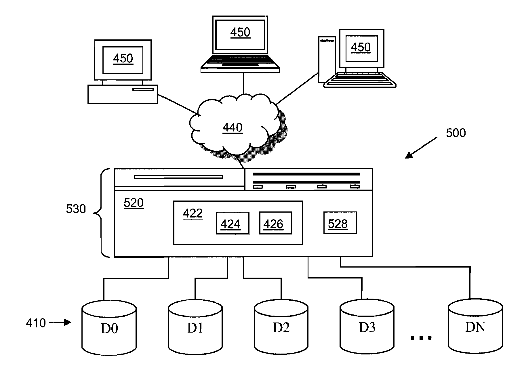
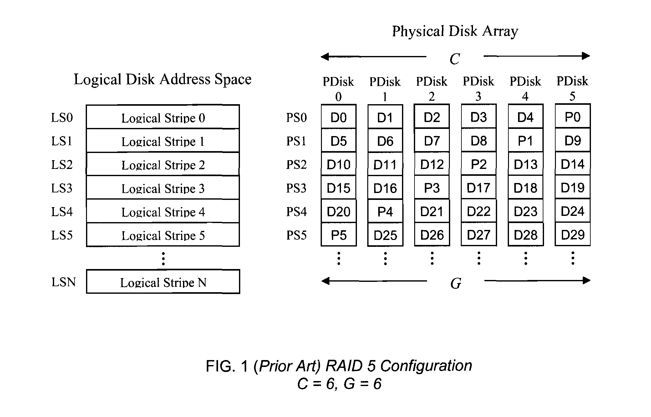
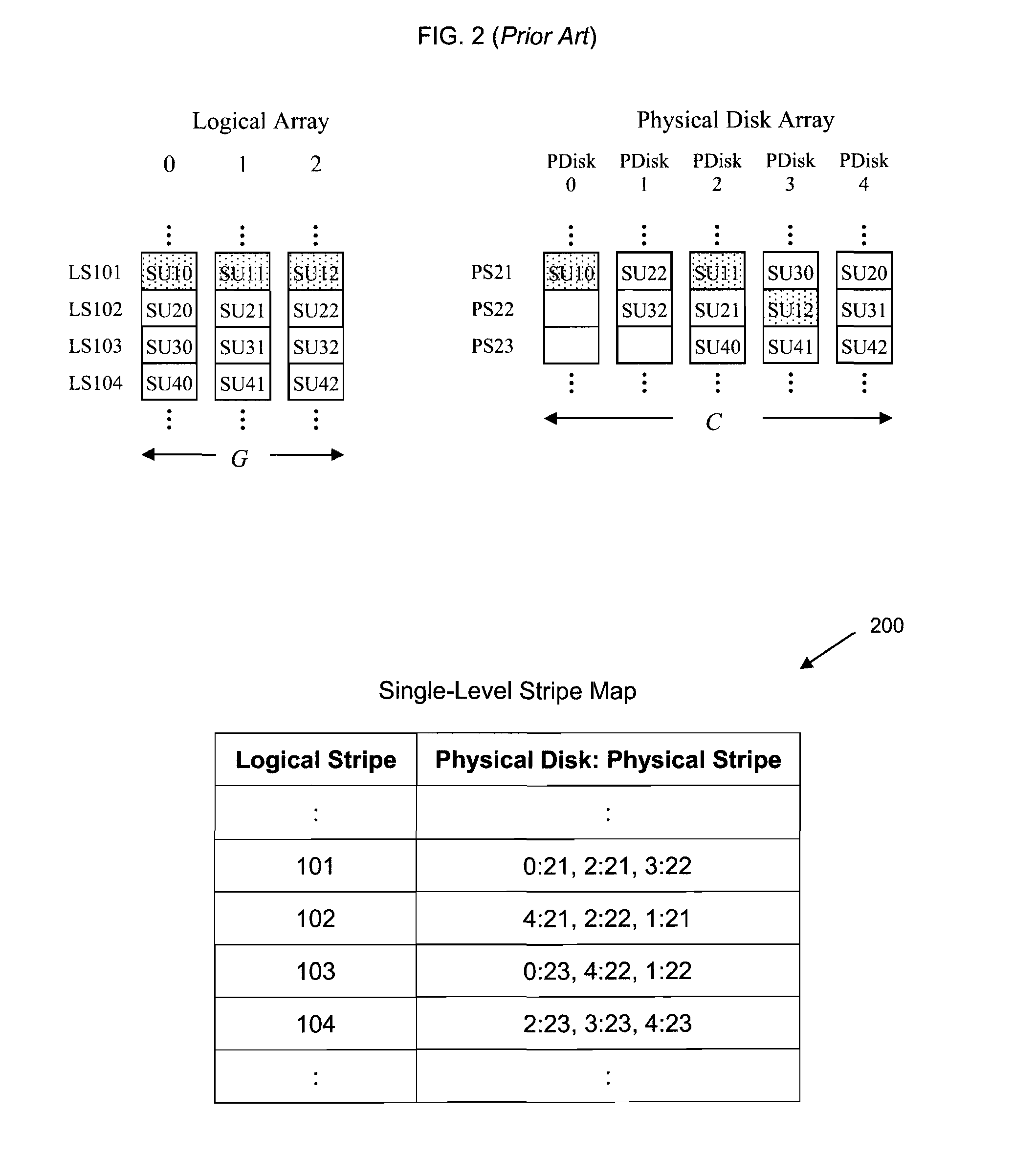
[0025]Embodiments of this disclosure relate generally to storage systems, and more specifically, parity declustered storage device arrays, such as a parity declustered redundant disk array, with partition groups. Today, high performance, fault-tolerant data storage systems (preferably in continuous operation) are in demand. To provide this, a storage system may include a storage device array, such as a disk array. A disk array is a set of physical disks with redundancy to protect against data lost. Embodiments of this disclosure provide a data layout for a disk array based on a partition group lookup table. A data layout is an arrangement of data and redundant information (such as parity) that allows the array to reconstruct the contents of one or more failed disks, thereby providing a level of fault tolerance. A data layout is constructed by partitioning units of the disk array into a collection of non-overlapping stripes.

[0026]This disclosure describes a novel mechanism for partit...


PUM


Abstract

This disclosure relates to parity declustered storage device arrays having partition groups. In an exemplary embodiment, the storage system includes a storage device array, such as disk array. Each storage device is divided into partitions. Each partition includes stripe units, such as hundreds or thousands of stripe units in exemplary embodiments. The storage system also includes a physical array controller coupled to the storage device array. In an exemplary embodiment, the array controller includes a partition group lookup table and stores and retrieves data and parity in the storage devices based on the partition group lookup table. In this exemplary embodiment, the array controller also includes a stripe lookup table and/or a log. In an exemplary embodiment, the partition group lookup table and the stripe lookup table take up less memory (e.g., by an order of magnitude) than a single-level stripe map conveying the same information.

Description

STATEMENT REGARDING FEDERALLY SPONSORED RESEARCH OR DEVELOPMENT[0001]This invention was made with United States Government support under Agreement No. HR0011-07-9-0002 awarded by DARPA. The Government has certain rights in the invention.FIELD OF THE INVENTION[0002]The present disclosure relates to storage systems, and more specifically, parity declustered storage device arrays, such as a parity declustered redundant disk array, with partition groups.BACKGROUND[0003]Redundant Array of Independent (or Inexpensive) Disks (RAID) is contemporarily used as an umbrella term for computer data storage configurations that divide user data and redundancy information among multiple hard disk drives in a disk array. Redundancy information enables the reconstruction of contents of a failed disk, with or without taking the storage system offline. Redundancy information may be, for example, a mirror copy of the user data (e.g., in RAID 1) or parity (e.g., in RAID 5).[0004]Mirroring can be prohibiti...

Claims


Application Information

Patent Timeline
IPC IPC(8): G06F12/00
CPCG06F11/1076
Inventor BECKER-SZENDY, RALPH A.DEENADHAYALAN, VEERAGUTHRIDGE, D. SCOTTWYLLIE, JAMES CHRISTOPHER
Owner IBM CORP
Why Eureka
Try Eureka