Apparatus, system, and method for using multi-level cell solid-state storage as single-level cell solid-state storage

a multi-level cell and solid-state storage technology, applied in the field of solid-state storage, can solve problems such as reducing the longevity of devices, and achieve the effect of increasing the guard band

Active Publication Date: 2010-09-16
SANDISK TECH LLC
View PDF99 Cites 64 Cited by
  • Summary
  • Abstract
  • Description
  • Claims
  • Application Information

AI Technical Summary

Benefits of technology

[0021]The invention may also include an apparatus to store information in a storage device comprising one or more multi-level memory cells. The apparatus may include instructions to receive a write command from a client, the write command comprising a logical block address. The apparatus may map the logical block address received from the client to one or more page pairs of the storage device, wherein each page pair comprises a lower page associated with a least significant bit (LSB) of a plurality of multi-level cells in the storage device, and an upper page associated with a most significant bit (MSB) of the multi-level cells.
[0022]The apparatus may also set the physical address for storing data associated with the write command to the physical address for the lower pages of the one or more page pairs, and write data associated with the write command received from the client to only one of the pages in each page pair of the one or more page pairs. Data in the lower page may be validated using audit data from the upper page. In addition, the apparatus may store audit data for the power page in the upper page of the page pair.
[0023]In certain embodiments, the apparatus searches for bit errors in the data stored in a lower page in response to determining that a number of detected ...

Problems solved by technology

While this increases the capacity, it also typically decreases the longevity of the device: the number of times it can be written; the number...

Method used


Image

  • Apparatus, system, and method for using multi-level cell solid-state storage as single-level cell solid-state storage
  • Apparatus, system, and method for using multi-level cell solid-state storage as single-level cell solid-state storage
  • Apparatus, system, and method for using multi-level cell solid-state storage as single-level cell solid-state storage

Examples


case 1

[0041]

[0042]Voltage: b′xy′

[0043]V0: b′10′

[0044]V1: b′11′

[0045]V2: b′01′

[0046]V3: b′00′

case 2

[0047]

[0048]Voltage: b′xy′

[0049]V0: b′11′

[0050]V1: b′10′

[0051]V2: b′01′

[0052]V3: b′00′

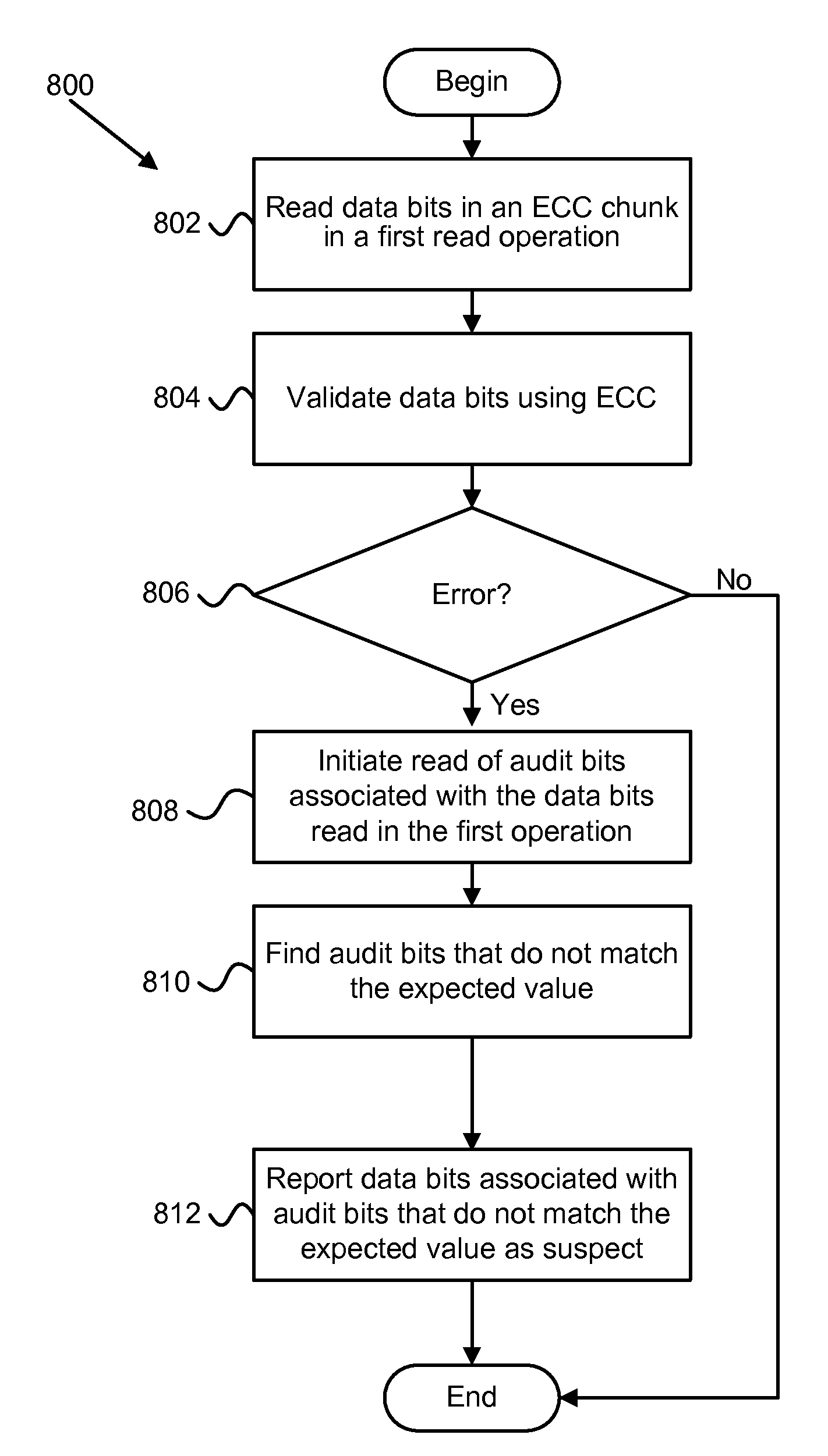
[0053]Other programming models may also be used. Another example of a programming model is discussed in connection with FIG. 6. In case 1, it can be seen that only the upper order bit (x) need be read to determine if the data written to V0 or V3. In case 2, it can be also seen that only the upper order bit (x) need be read to determine if the data written to V0 or V3.

[0054]Case 1 may offer advantages over case 2. In case 1, a read of the lower order bit (y) allows an immediate determination that the quality of the data in the cell may be suspect. If it is a “0”, it is unlikely that any read or program disturbs have affected the data value. Whereas the “y” values for an entire region of memory could be read simultaneously, these could be checked asynchronously to the reads of the “x” values. Therefore a background process could periodically audit the “y” values throughout the array, and depending on...


PUM


Abstract

An apparatus, system, and method are disclosed for storing information in a storage device that includes multi-level memory cells. The method involves storing data that is written to the storage device in the LSBs of the multi-level memory cells, and storing audit data in the MSBs of the multi-level memory cells. The audit data can be read separately from the data and used to determine whether or not there has been any unintended drift between states in the multi-level cells. The audit data may be used to correct data when the errors in the data are too numerous to be corrected using error correction code (ECC). The audit data may also be used to monitor the general health of the storage device. The monitoring process may run as a background process on the storage device. The storage device may transition the multi-level memory cells to operate as single-level memory cells.

Description

CROSS-REFERENCE TO RELATED APPLICATIONS[0001]This application claims the benefit of U.S. Provisional Patent Application No. 61 / 160,258 entitled “Apparatus, System, and Method for Using Multi-Level Cell Solid-State Storage as Single-Level Cell Solid-State Storage,” filed Mar. 13, 2009.FIELD OF THE INVENTION[0002]This invention relates to solid-state storage and more particularly relates to multi-level cell solid-state storage.BACKGROUNDDescription of the Related Art[0003]To increase the capacity of storage in flash memory, multiple bits are stored in a single memory cell. While this increases the capacity, it also typically decreases the longevity of the device: the number of times it can be written; the number of times it can be read per write; and the ability of the data to be error free when the device is unpowered or operating at high temperature, etc.[0004]The majority of the non-volatile memory market is driven in this direction by consumer products where capacity is key and th...

Claims


Application Information

Patent Timeline
IPC IPC(8): G06F12/16G06F11/07H03M13/05G06F12/00G06F11/10
CPCG11C16/10G11C16/26G11C29/00G11C2211/5641G11C16/0483G11C11/5621G11C11/5628G11C11/5642G06F11/1072
Inventor THATCHER, JONATHANFLYNN, DAVIDBARNES, ETHANSTRASSER, JOHNWOOD, ROBERTZAPPE, MICHAEL
Owner SANDISK TECH LLC
Why Eureka
Try Eureka