
Nonvolatile memory devices including multiple user-selectable program modes and related methods of operation

Inactive Publication Date: 2008-07-17
SAMSUNG ELECTRONICS CO LTD
View PDF7 Cites 69 Cited by
  • Summary
  • Abstract
  • Description
  • Claims
  • Application Information

AI Technical Summary

Benefits of technology

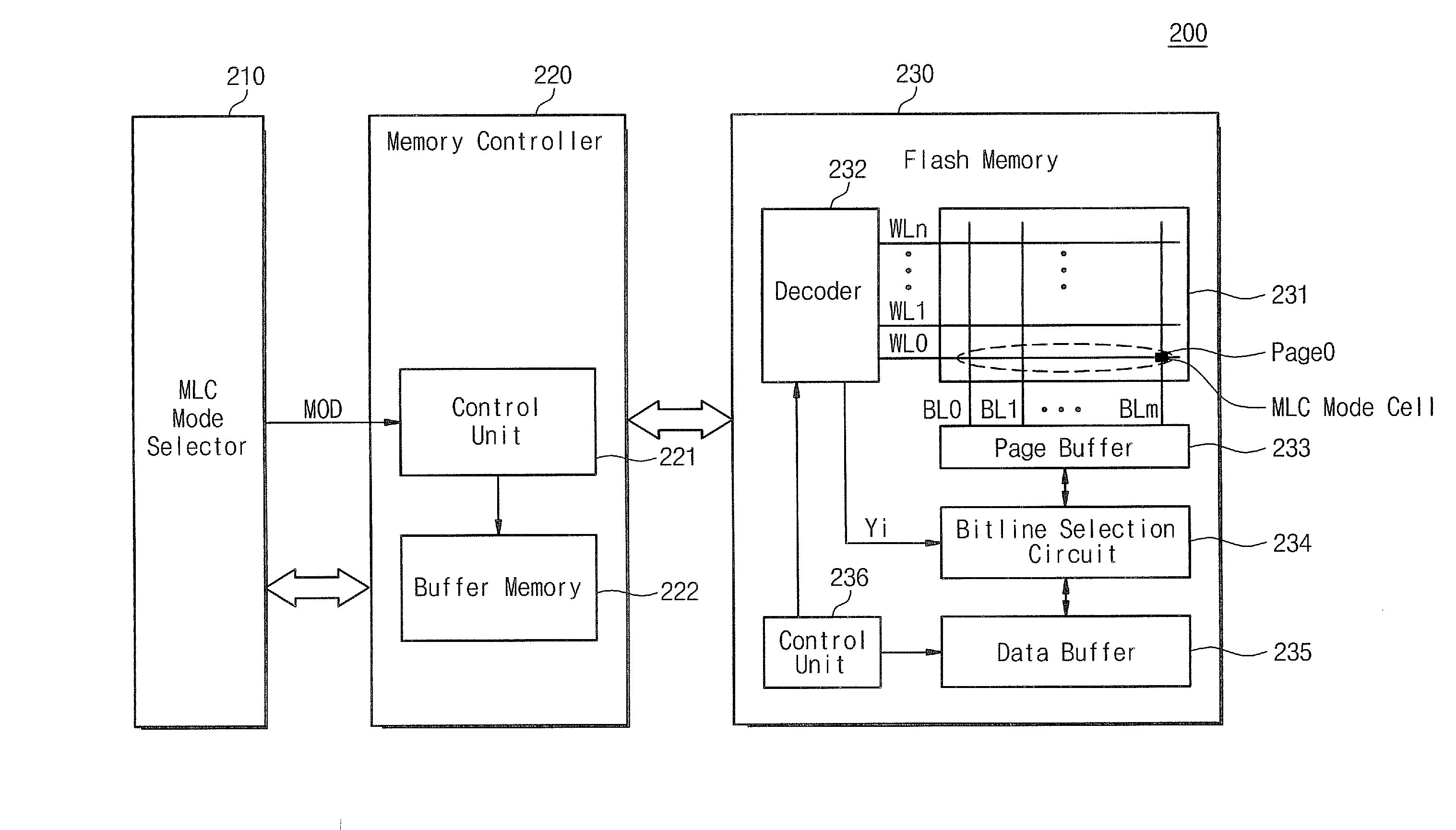
[0030]In other embodiments, the memory controller may include a control unit configured to control programming of the flash memory device in the SLC mode or the MLC mode based on the mode selection signal, and a buffer memory unit configured to store data to be programmed into t

Problems solved by technology

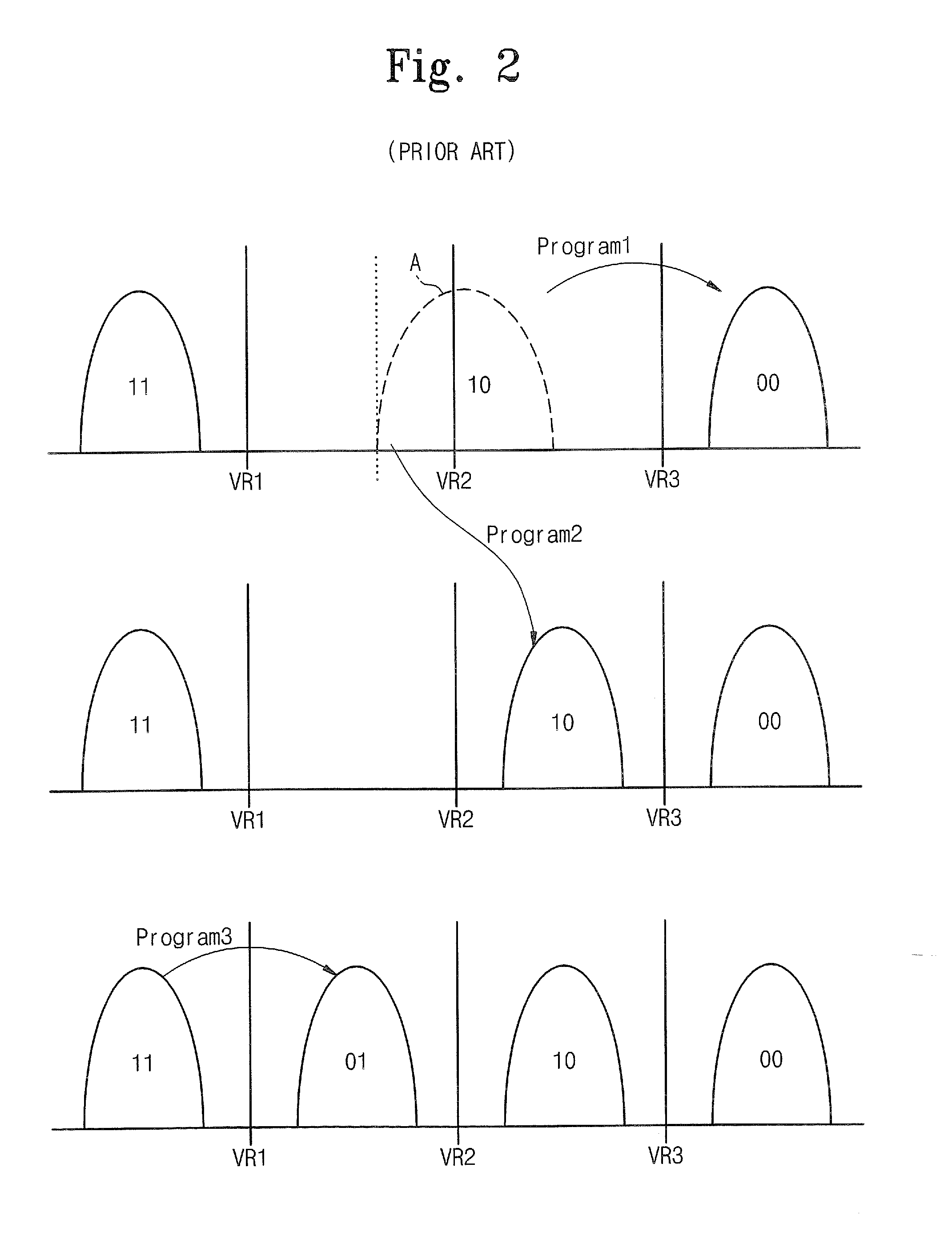
For example, during a programming operation, an error may be generated while programming an MSB even though there has been no error in programming an LSB.
In this case, the LSB data may be inadvertently lost.
Especially for data such as security data where data integrity may be important, errors during the programming operation may be problematic.
Also, a user may not use the full data storage capacity of a flash memory device.

Method used


Image

  • Nonvolatile memory devices including multiple user-selectable program modes and related methods of operation
  • Nonvolatile memory devices including multiple user-selectable program modes and related methods of operation
  • Nonvolatile memory devices including multiple user-selectable program modes and related methods of operation

Examples


Embodiment Construction

[0041]The present invention is described more fully hereinafter with reference to the accompanying drawings, in which embodiments of the invention are shown. This invention may, however, be embodied in many different forms and should not be construed as limited to the embodiments set forth herein. Rather, these embodiments are provided so that this disclosure will be thorough and complete, and will fully convey the scope of the invention to those skilled in the art. In the drawings, the sizes and relative sizes of layers and regions may be exaggerated for clarity.

[0042]It will be understood that when an element is referred to as being “on,”“connected to” or “coupled to” another element, it can be directly on, connected or coupled to the other element or layer or intervening elements may be present. In contrast, when an element is referred to as being “directly on,”“directly connected to” or “directly coupled to” another element, there are no intervening elements present. Like number...


PUM


Abstract

A memory device includes a flash memory, a memory controller, and an MLC mode selector. The flash memory includes at least one memory cell configured to store multi-bit data therein. The MLC mode selector is configured to generate a mode selection signal indicating whether to store single-bit data or multi-bit data in the memory cell responsive to a user selection. The memory controller is configured to operate the flash memory in a single-level cell (SLC) program mode to store the single-bit data or a multi-level cell (MLC) program mode to store the multi-bit data based on the mode selection signal from the MLC mode selector. The memory device may be configured to store program mode information for the memory cell indicating whether the single-bit data or the multi-bit data is stored therein. Related systems and methods of operation are also discussed.

Description

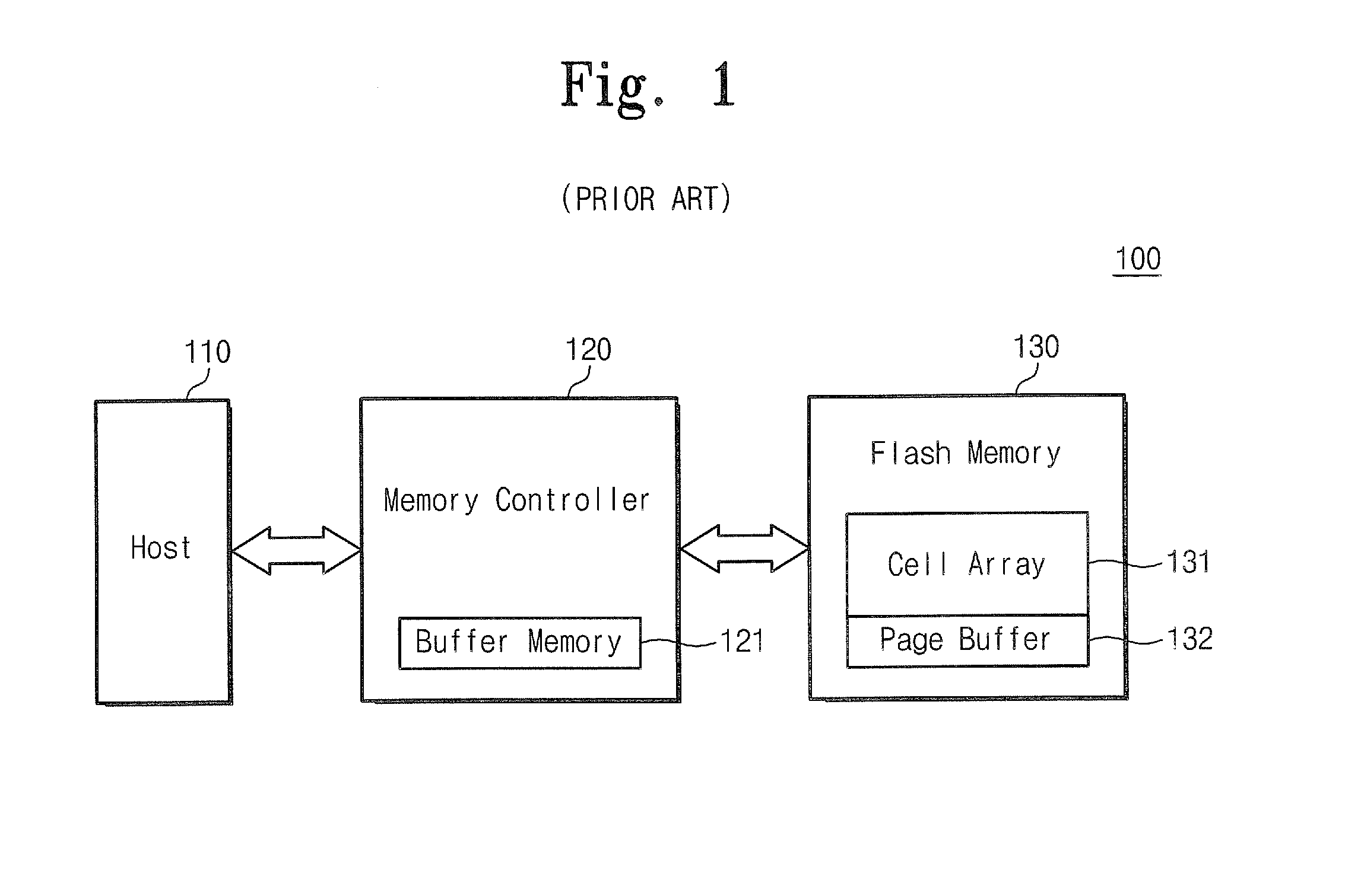
CROSS-REFERENCE TO RELATED APPLICATIONS[0001]This application claims priority under 35 U.S.C. § 119 from Korean Patent Application No. 10-2007-05252 filed on Jan. 17, 2007, the disclosure of which is hereby incorporated by reference herein in its entirety.FIELD OF THE INVENTION[0002]The present invention relates to the field electronics, and more particularly, to electronic memory systems and.BACKGROUND OF THE INVENTION[0003]Portable apparatuses employing nonvolatile memories may be increasingly common. For example, nonvolatile memories may be used as storage units in MP3 players, digital cameras, mobile phones, camcorders, flash cards, solid state disks (SSDs), and so on.[0004]As the use of nonvolatile memory-based storage units increases, memory capacities may also increase. One way to increase memory capacity may involve a multi-level cell (MLC) mode that may store multiple data bits in a unit memory cell.[0005]FIG. 1 is a block diagram of a conventional memory system. Referring ...

Claims


Application Information

Patent Timeline
IPC IPC(8): G06F12/00
CPCG11C2211/5641G11C11/5628A47C1/12A47C4/045A47C7/425A47C7/0213
Inventor LEE, BONG-RYEOL
Owner SAMSUNG ELECTRONICS CO LTD
Learn More