Pipe-bending alignment device

a technology of alignment device and pipe, which is applied in the direction of mechanical measurement arrangement, instruments, and mechanical means, etc., can solve the problems of inconvenient installation, unsatisfactory dogging, and difficult to ensure that the bend being introduced in the pipe lies in the plane defined by a prior bend,

Inactive Publication Date: 2002-05-14
GODIN JEFFREY L
View PDF15 Cites 32 Cited by
  • Summary
  • Abstract
  • Description
  • Claims
  • Application Information

AI Technical Summary

Problems solved by technology

For example, inadvertently twisting the pipe or shifting the reference plane between the first and second bends will result in the undesired dogging.
Devices of this type have a serious drawback in that they have no means of indicating or tracking a bend-plane, thereby making it difficult to ensure that a bend being introduced in a pipe lies in the plane defined by a prior bend.
A major disadvantage of the Traubmann device is that it can indicate direction only for the horizontal projection of the longitudinal axis of the pipe segment to which the device is attached.
Of course, this problem arises with any bend being guided by the Traubmann device that is supposed to be in a defined plane; this device does not provide any way of ensuring that the bend is indeed in the desired plane.
It is also noted that simply having to move and reclamp the Traubmann device is time-consuming.
It means that for multiple bends not only does one have to move the pipe-bending tool along the pipe (common to all pipe-bending operations), but one also has to repeatedly reposition the guide device, which in any event does not provide guidance for ensuring that the new bend-plane is coincident with an earlier one.
Although this does help achieve this goal, the Weldy et al. device is limited to bends in the same plane.
It does not address the need that often arises wherein a bend is to be out of a plane by a set angle.
Furthermore, because of the nature of the means by which it is attached to the pipe, it can inadvertently be "cocked" by a few degrees, i.e., as attached to the pipe, its longitudinal axis may not be exactly parallel to the pipe axis, a

Method used


Image

  • Pipe-bending alignment device
  • Pipe-bending alignment device
  • Pipe-bending alignment device

Examples


Embodiment Construction

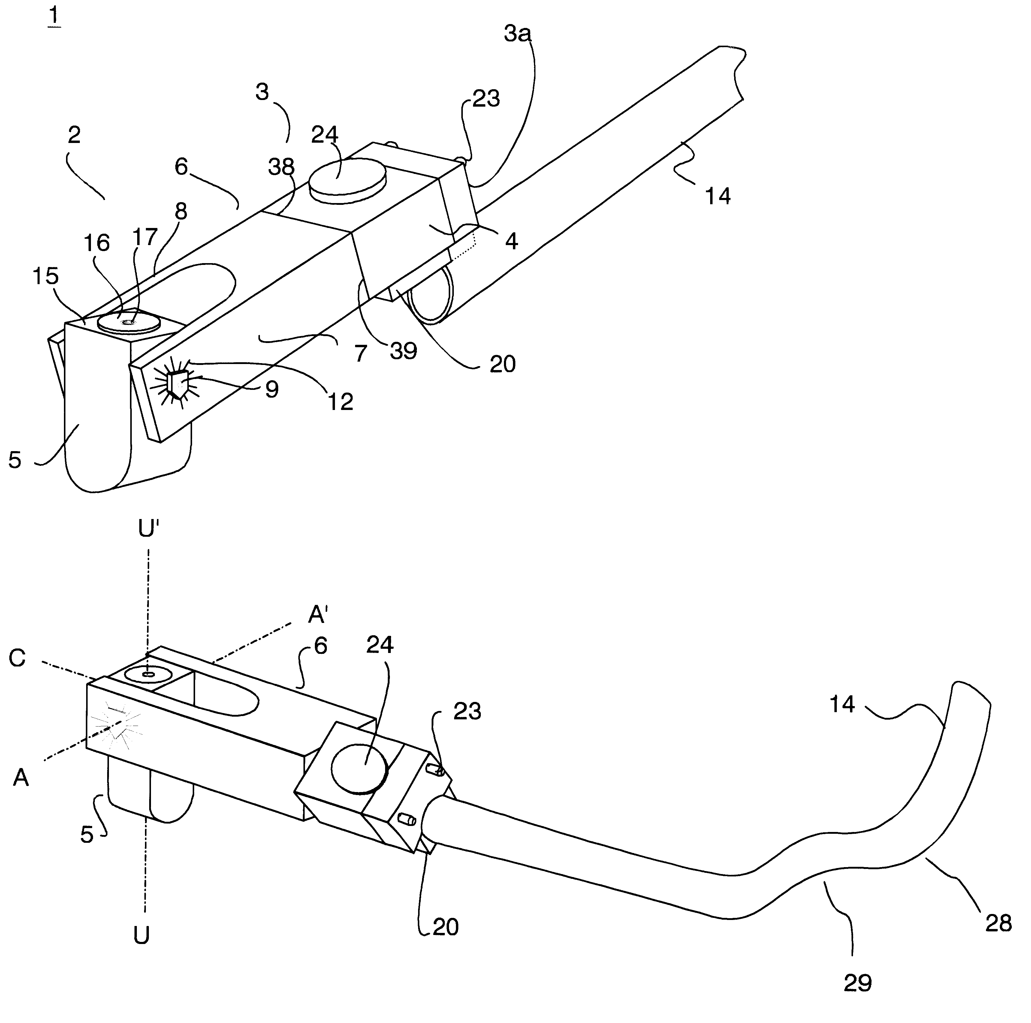
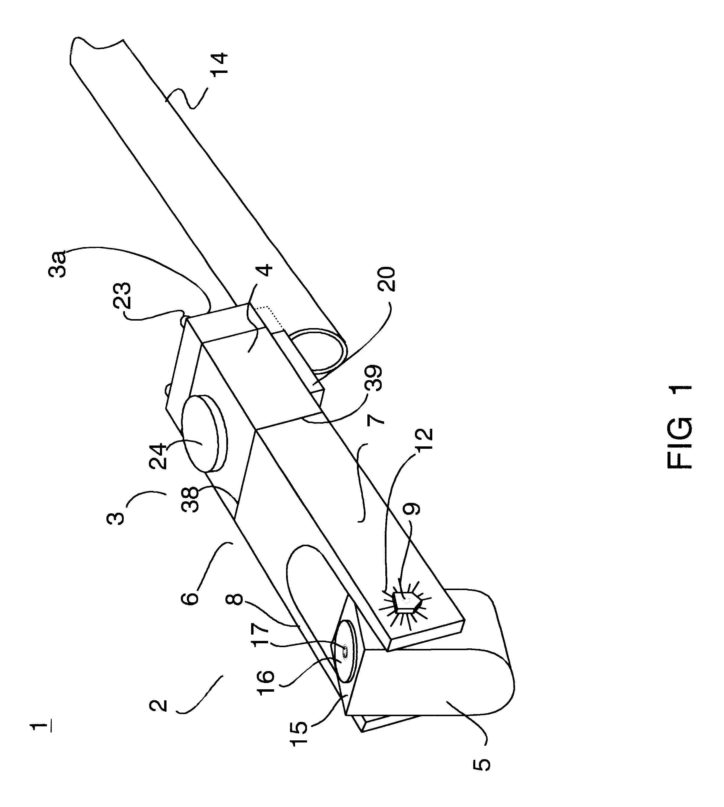
The bend-angle-and-bend-plane guide 1 of the present invention is shown in its Preferred Embodiment in FIG. 1. It consists of two main parts: a gauge section 2 and a mounting section 3. A mounting clamp 4 located at a proximal end 3a of the mounting section 3 provides the means by which the guide 1 is affixed to a pipe 14, the pipe to be bent (typically by use of a bending tool, such as is depicted in FIG. 4a by the stylized bending tool 50).

The mounting section 3 is displayed in more detail in FIG. 3a and FIG. 3b, which illustrate that the clamp 4 includes a removably attached outer jaw 19, a removably attached inner jaw 20, and a thumbscrew 24, the clamp-tightening means used in the Preferred Embodiment. This is illustrated best in FIG. 3b, which shows a cutaway piece of the pipe 14 clamped between an outer-jaw clamping surface 21 and an inner-jaw clamping surface 22. The outer-jaw clamping surface 21 is a concave cylindrical surface having a radius of curvature r equal to that of...


PUM

PropertyMeasurementUnit
Angleaaaaaaaaaa
Angleaaaaaaaaaa
Angleaaaaaaaaaa

Abstract

An economical, compact guide for introducing multiple bends in one or more planes in a pipe, conduit, or other tube-like item. The guide has a gauge section rotatably attached to a mounting section and is affixable by means of a non-deforming clamp to the end of a pipe segment to be bent. The gauge section has a bend-angle gauge and a bend-plane level. The bend-angle gauge is a plumb arm mounted so as to measure and indicate the bending of a pipe to any degree of bend. The bend-plane guide is a 360° level mounted on an upper face of the plumb arm. Multiple bends are made in the pipe segment without removing or re-aligning the guide. This ensures that the initial reference position is maintained throughout the bending process and ensures that all bends are in the proper bend-plane, thus avoiding "dogging" between successive bends. Multiple successive bend-planes also may be established without removing or re-aligning the guide on the pipe, by rotating the gauge section of the guide relative to the mounting section by the magnitude of the desired out-of-plane angle.

Description

1. Field of InventionThe present invention relates to the field of fabrication and construction. In particular, the invention relates to the fields of plumbing and wiring. More particularly, the invention relates to the installation of pipe, conduit, and other pipe-like material, such as hydraulic and pneumatic tubing. Still more particularly, the invention relates to the accurate bending, for shaping and routing, of pipe, conduit, and other tube-like material in multiple planes.2. Prior ArtIn many fields, it is frequently necessary to bend pipe, conduit, and other tube-like items (hereinafter "pipe"). The need arises, for example, in the installation of electrical equipment, plumbing systems, and, generally, in construction work. Typically, a single pipe will have to be bent several times. There are two components of the bending process that must be carefully controlled when introducing multiple bends in a pipe: the bend-angle and the bend-plane. Thus, the pipe-bender must be able ...

Claims


Application Information

Patent Timeline
IPC IPC(8): B21D7/00B21D7/06
CPCB21D7/063
Inventor GODIN, JEFFREY L.
Owner GODIN JEFFREY L
Why Eureka
Try Eureka